
Spoke edge geometry for a non-pneumatic tire

a non-pneumatic or hybrid tire technology, applied in the direction of wheel attachments, dough shaping, manufacturing tools, etc., can solve the problems of affecting the operability of the tire, too being undesirable, and reducing the wear resistance of the tir

Active Publication Date: 2013-09-19
MICHELIN RECH & TECH SA +2
View PDF2 Cites 33 Cited by
  • Summary
  • Abstract
  • Description
  • Claims
  • Application Information

AI Technical Summary

Benefits of technology

The present invention provides an improved spoke edge geometry for a non-pneumatic tire that is less prone to fatigue when used. The spoke edge geometry is designed to reduce bending stresses and prevent stress risers, which can enhance the durability of the tire. The invention also includes a new and improved mold design that allows for the manufacturing of the tire's spokes. The spokes are formed by pouring a polyurethane liquid into a rotational mold and curing it. The spokes are grouped in pairs and consistently spaced from each other, which helps to reduce fatigue failure. The endurance of the spokes and the operability of the tire depend significantly on the accuracy of the geometry and the absence of stress risers caused by manufacturing flaws.

Problems solved by technology

This creates a risk of fatigue failure for the spokes.
This too can be undesirable for reasons that will be discussed below.
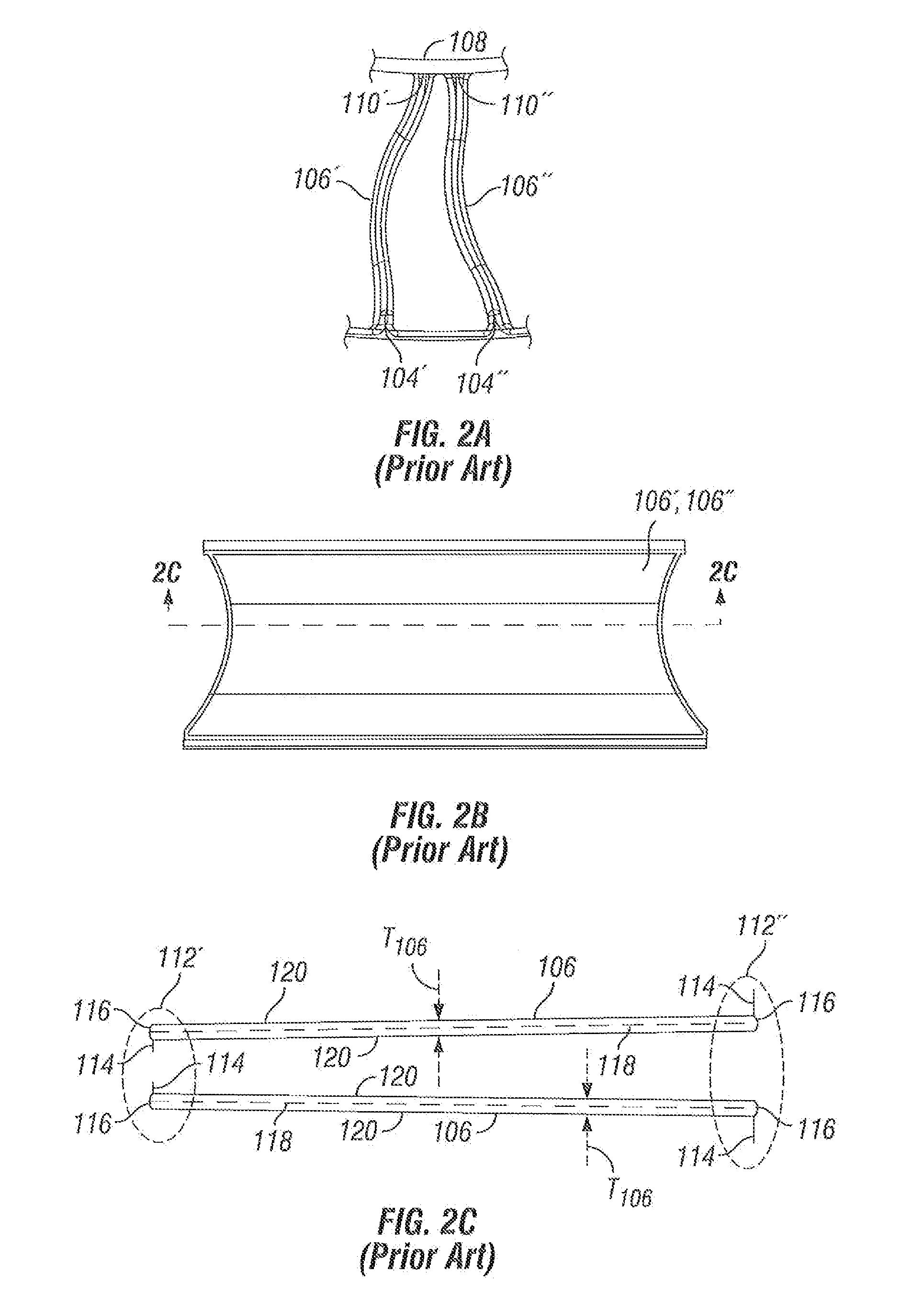
These manufacturing flaws then lead to crack initiation and propagation that can cause the spoke 106 to fail, undesirably impairing the operability of the tire 100.
The location of these flaws is less than optimal because they are found near the edge 112 of the spokes 106 where they bend, creating high strains and stresses which cause cracks to initiate.
Put into other words, the flash is oriented in its most rigid configuration relative to the bending of the spokes making it more susceptible to cracking and this adds to the susceptibility of the spoke to fail 106.
So this too can initiate cracks that could cause the spoke to fail.
Mold mismatch may occur in any, all or none of the cavities of the previous mold construction depending on a host of variables such as core deflection due to mold processing conditions, improper machining, and tolerance stack ups, etc.

Method used


Image

  • Spoke edge geometry for a non-pneumatic tire
  • Spoke edge geometry for a non-pneumatic tire
  • Spoke edge geometry for a non-pneumatic tire

Examples


Embodiment Construction

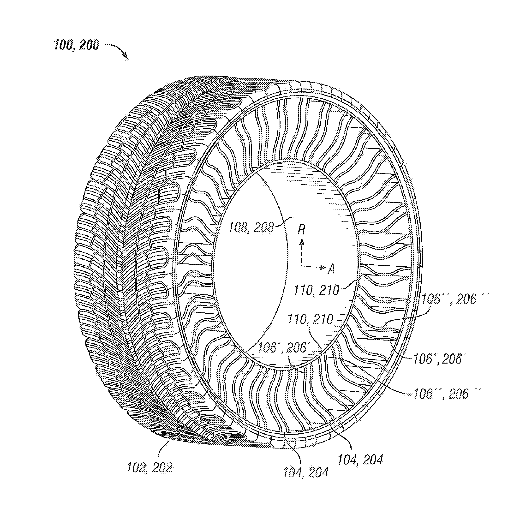
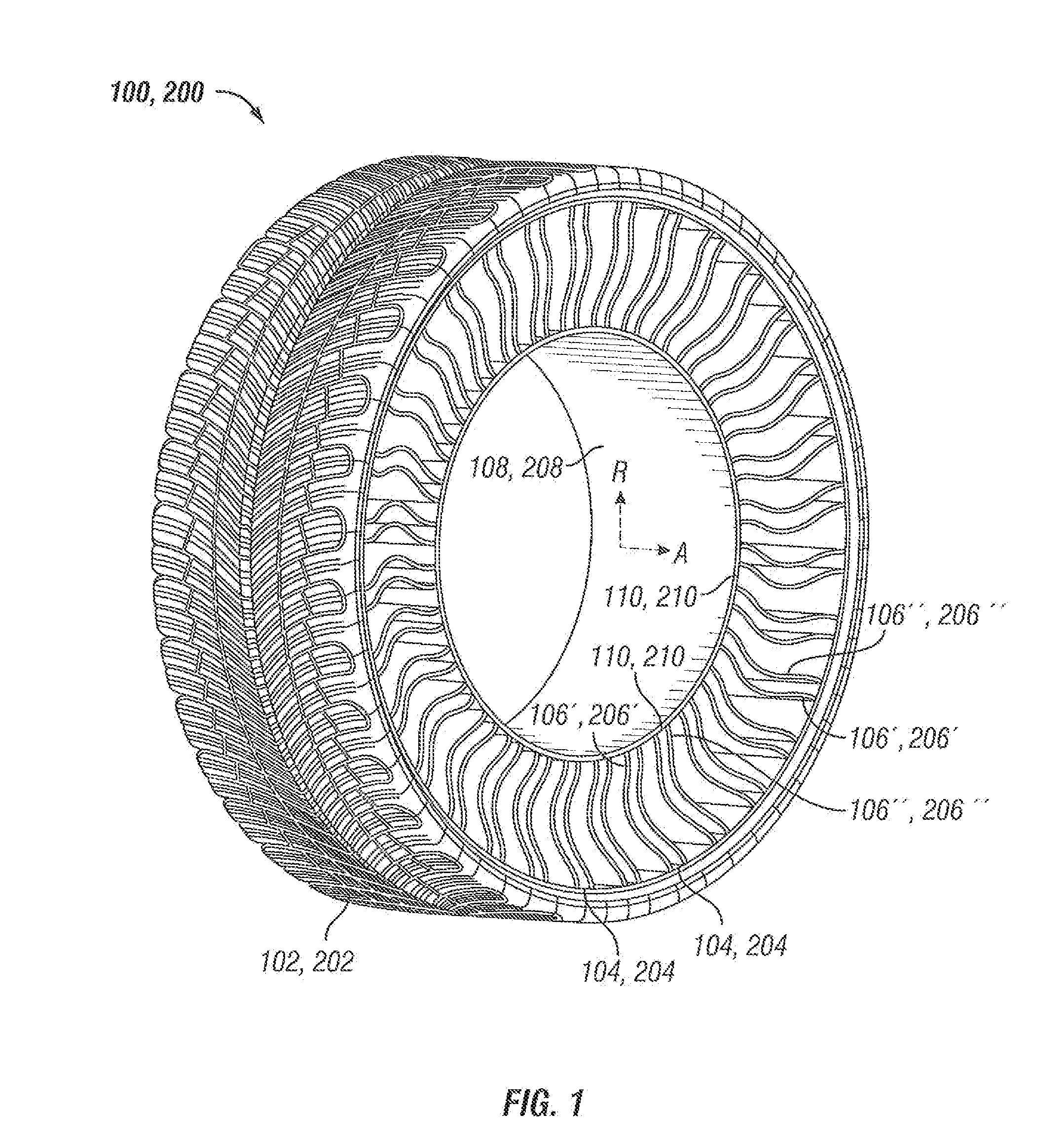
[0049]Reference will now be made in detail to embodiments of the invention, one or more examples of which are illustrated in the Figures. Each example is provided by way of explanation of the invention, and not meant as a limitation of the invention. For example, features illustrated or described as part of one embodiment can be used with another embodiment to yield still a third embodiment. It is intended that the present invention include these and other modifications and variations. It should be noted that for the purposes of discussion, only a portion of the exemplary tire embodiments may be depicted in one or more of the figures. Reference numbers are used in the Figures solely to aid the reader in identifying the various elements and are not intended to introduce any limiting distinctions among the embodiments. Common or similar numbering for one embodiment indicates a similar element in the other embodiments.

[0050]Given the tendency of the previous mold construction to produc...


PUM

PropertyMeasurementUnit
Thicknessaaaaaaaaaa
Thicknessaaaaaaaaaa
Angleaaaaaaaaaa

Abstract

The present invention provides improved spoke edge geometry for a non-pneumatic or hybrid tire that is less prone to fatigue when used. The present invention also provides a way to manufacture such geometry in a mold, In particular the spoke edge geometry is provided with a reduced cross-section that reduces the bending stresses locally and allows a unique mold construction that changes the placement and orientation of potential flash and reduces other potential molding flaws when a liquid such as polyurethane is introduced into the cavity of the mold to form a spoke. This change results in a reduction in the possibility of a stress riser being found near the edge of the spoke, enhancing the durability of the tire.

Description

PRIORITY CLAIM[0001]This application claims the benefit of previously filed U.S. Provisional Patent Application entitled “Spoke Edge Geometry for a Non-Pneumatic Tire”, assigned U.S. Ser. No. 61 / 379,351, filed Sep. 1, 2010, and which is incorporated herein by reference in its entirety for all purposes.BACKGROUND OF THE INVENTION[0002]1. Field of the Invention[0003]The present invention provides improved spoke edge geometry for a non-pneumatic or hybrid tire that is less prone to fatigue when used. The present invention also provides a way to manufacture such geometry in a mold. In particular, the spoke edge geometry is provided with a reduced crass-section that reduces the bending stresses locally and allows a unique mold construction that changes the placement and orientation of potential flash and reduces other potential molding flaws when a liquid such as polyurethane is introduced into the cavity of the mold to form a spoke. This change results in a reduction in the possibility ...

Claims


Application Information

Patent Timeline
IPC IPC(8): B60B9/26B29D30/02
CPCB29D30/02B60C2007/146B60C7/22B60B9/26B60C7/146B29C41/042B29C41/38B60C7/14B60C7/107
Inventor CRON, STEVEN M.DOTSON, MICHAEL EDWARDMILES, KEVIN C.RHYNE, TIMOTHY BRETT
Owner MICHELIN RECH & TECH SA
Learn More