Eureka AIR delivers breakthrough ideas for toughest innovation challenges, trusted by R&D personnel around the world.

Switch unit and power generation system thereof

Active Publication Date: 2013-09-12
DELTA ELECTRONICS INC
View PDF5 Cites 17 Cited by
  • Summary
  • Abstract
  • Description
  • Claims
  • Application Information

AI Technical Summary

Benefits of technology

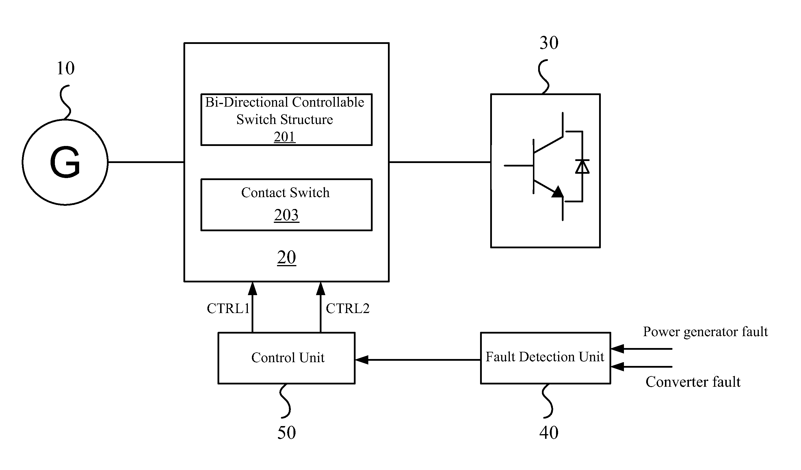
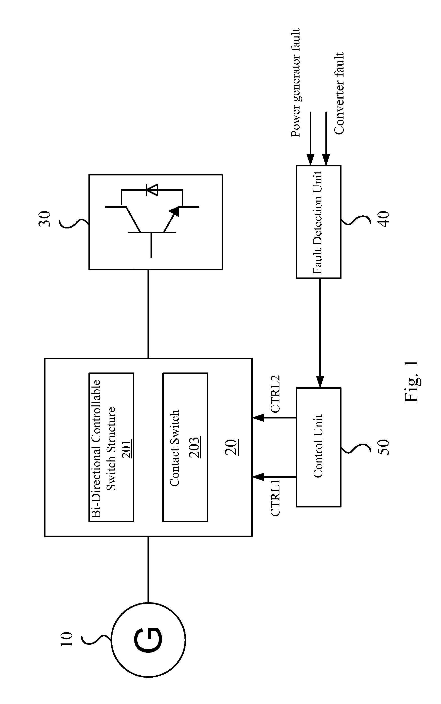
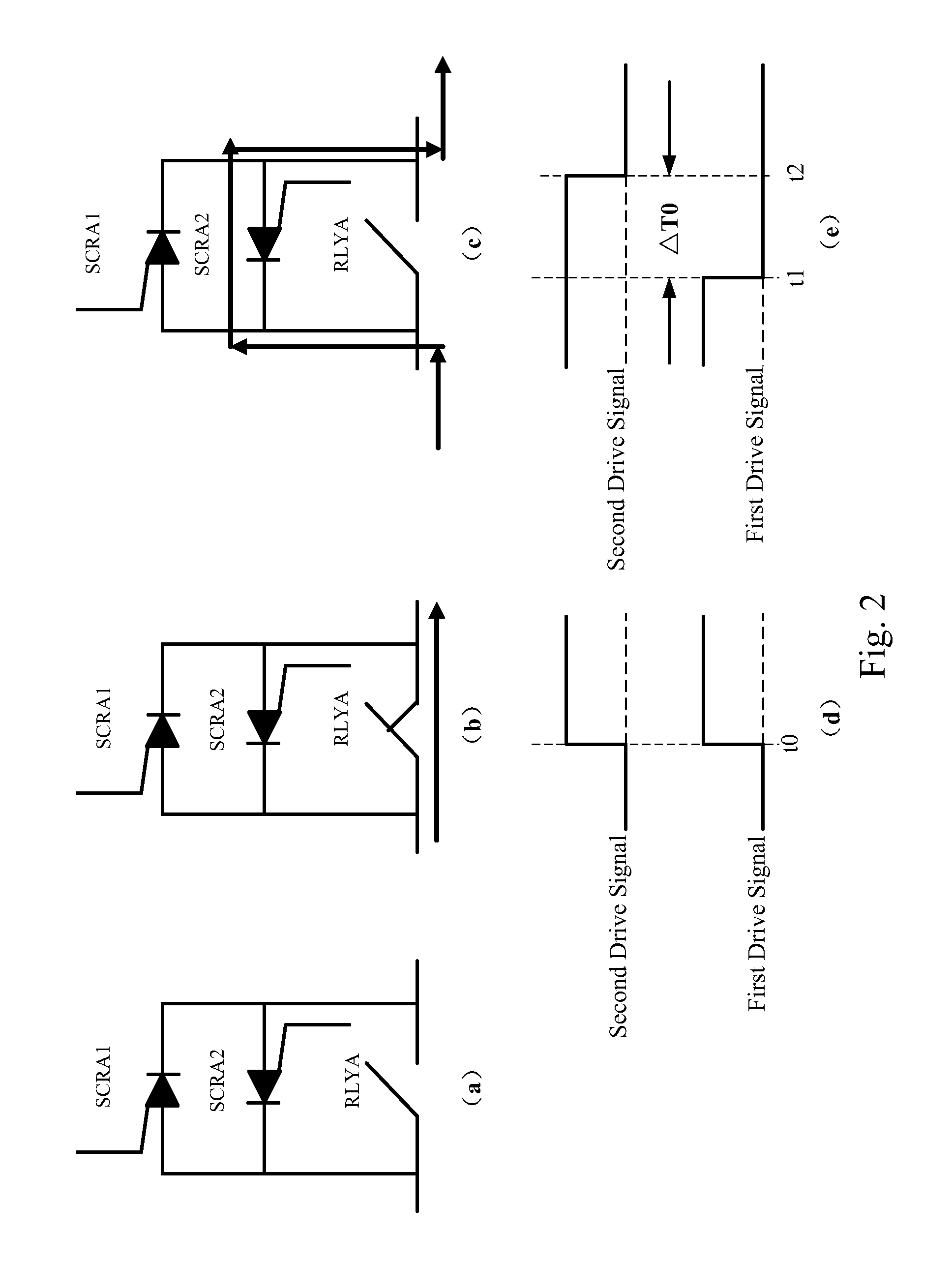
This patent describes a switch unit that includes a contact switch and a bi-directional controllable switch structure. The switch unit allows for quick disconnection of a power generation system when there is a problem with the electrical connection. The bi-directional controllable switch structure provides a commutation bypass for the contact switch, which protects it from damage during the turn-off operation. The switch unit also effectively eliminates the arc voltage loaded on the contact switch, which increases its life span. Overall, this switch unit improves the stability and performance of the power generation system.

Problems solved by technology

When the system fails, if the wind power converter is directly connected with the wind turbine, the rate of rotation of the wind turbine is limited in a range only by adding external loadings.
However, since the wind turbine is directly and continuously connected with the converter, and the power of the dump loads is limited, the voltage limiting capacity of the dump loads is also limited.
Furthermore, the switching response rate of the dump loads is slow, so that once the system fails unexpectedly, the reliability thereof cannot be ensured.
However, such a contact switch is mostly applied to a high power-grade wind power generation system, and the cost of a contact switch having an arc extinction function is high.
Additionally, if a controllable contact switch is directly used as the input switch (having no arc extinction device), since the wind turbine winding itself has a large equivalent inductance (for example, a 20 kW power generator has an equivalent inductance of about 18 mH to 40 mH), at the point in time that the switch is turned off, the energy stored by the equivalent inductance cannot be released in time, so that the generated arc voltage is loaded on two ends of the contact switch and thus the contact switch cannot operate normally or the usage life of the contact switch is reduced.

Method used


Image

  • Switch unit and power generation system thereof
  • Switch unit and power generation system thereof
  • Switch unit and power generation system thereof

Examples


Embodiment Construction

[0038]In order to make the technical contents of the present disclosure more detailed and more comprehensive, various embodiments of the present disclosure are described below with reference to the accompanying drawings. Wherever possible, the same reference numbers are used in the drawings and the description to refer to the same or like parts. However, those of ordinary skills in the art should understand that the embodiments described below are not used for limiting the scope of the present disclosure. Moreover, the accompanying drawings are only illustrative and are not made according to the original size.

[0039]In the embodiments and the claim of the present disclosure, the description relating to “coupled with” may refer to that a component is indirectly connected to another component through other components, and may also refer to that a component is directly connected to another component without using other components.

[0040]In the embodiments and the claim of the present dis...


PUM


Abstract

The present disclosure provides a switch unit and a power generation system thereof. The switch unit includes a contact switch having a main contact and a control terminal, where the control terminal receives a first drive signal to turn on the contact switch; and a bi-directional controllable switch structure, which is connected in parallel to two ends of the main contact of the contact switch and receives one or more second drive signals to turn on the switch structure. When the switch unit performs a turn-off operation, the bi-directional controllable switch structure provides a commutation bypass for the contact switch, so as to protect the contact switch.

Description

RELATED APPLICATIONS[0001]This application claims priority to Chinese Application Ser. No. 201210059575.1, filed Mar. 8, 2012, which is herein incorporated by reference.BACKGROUND[0002]1. Field of Invention[0003]The present disclosure relates to power electronic technology. More particularly, the present disclosure relates to a switch unit including a contact switch.[0004]2. Description of Related Art[0005]With the ever-increasing seriousness of energy-related problems in recent times, the development of new ways in which to generate energy (e.g., wind energy, solar energy, etc.) is attracting the attention of those involved in research and development in various areas. In a power generation system, the amplitude and frequency of the output AC (alternating current) of the power generator is not consistent with those of the AC power grid. Therefore, the output AC power of the power generator is converted into a DC (direct current) power by means of a converter, and subsequently the D...

Claims


Application Information

Patent Timeline
IPC IPC(8): H02H7/12
CPCH02H7/065H01H9/542H02H7/222H02H7/12
Inventor ZHOU, ZHI-JIANTONG, CHENGCHEN, PENGXU, ZHEN-QINGCHEN, SHUAN-YONG
Owner DELTA ELECTRONICS INC
Why Eureka
Eureka Blog
Learn More