
Full Flow Gun System for Monobore Completions

a monobore and full flow technology, applied in the field of perforating guns, can solve the problems of reducing or defeating the advantage of monobores

Active Publication Date: 2013-09-12
BAKER HUGHES INC
View PDF7 Cites 3 Cited by
  • Summary
  • Abstract
  • Description
  • Claims
  • Application Information

AI Technical Summary

Benefits of technology

The perforating gun assembly described in this patent allows for flow through the gun and does not require a full bore isolation valve after firing. The assembly can be run into a hole on a string and left in position. It uses pressure pulses to open a poppet and initiate detonation. The assembly can be used in both vertical and deviated completions and can facilitate future intervention work throughout the gun. It also mentions the use of swelling packers for zonal isolation between gun sections.

Problems solved by technology

Suspending the guns within the monobore creates a restriction through which the production fluids must flow and thereby reduces or defeats the advantage of having a monobore.

Method used


Image

  • Full Flow Gun System for Monobore Completions
  • Full Flow Gun System for Monobore Completions

Examples


Embodiment Construction

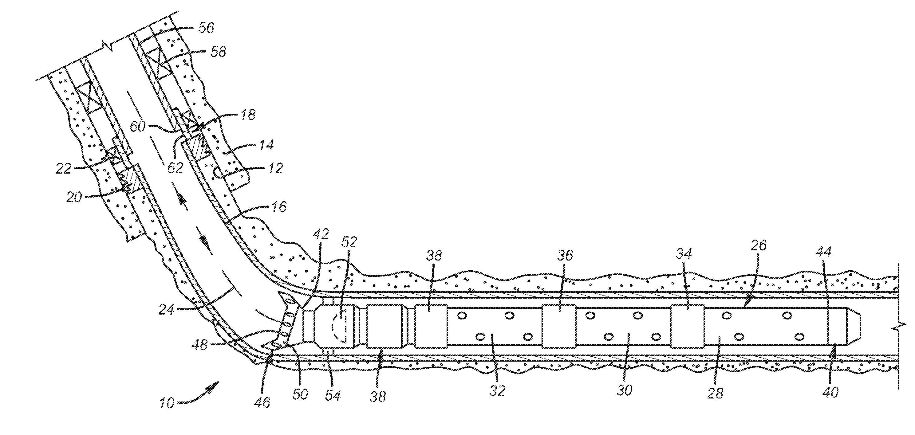
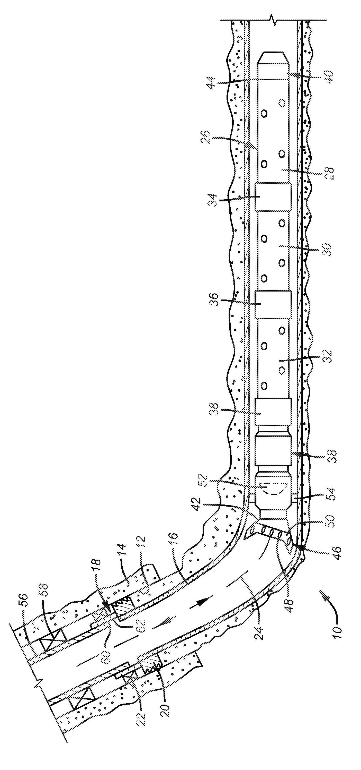
[0008]Referring to the Figure, a horizontal wellbore 10 has a casing 12 that is cemented at 14. A production liner 16 is hung off the casing 12 using a liner hanger 18 that has slips 20 and a seal 22. Dashed line 24 and the arrows that are on it schematically represent a running string and running tool that delivered and released from the gun assembly 26. Gun 26 has sections 28, 30 and 32 that schematically appear in the FIG. but can be in different zones in a fairly long assembly of the gun 26. Isolators such as 34, 36 and 38 can be used. Preferably they are swelling packers that react to well fluids or added fluids to swell and seal off the liner 16 at the desired locations to isolate the various zones. Two or more zones are contemplated as well as a single zone where the packers 34, 36 and 38 can be eliminated.

[0009]The schematically represented firing head assembly 38 includes a chamber that houses the firing pin with a poppet valve that opens for pressure access of well fluids ...


PUM


Abstract

A perforating gun assembly for a monobore application eliminates a full bore isolation valve or other component that has a limiting internal or external dimension and is designed to remain in position after firing. The assembly is run into the hole on a string with a running tool and left in position with the string and the running tool removed. Pressure pulses communicate with a detonation control system to open a poppet to pressurize a chamber with a firing head. It should be noted that other types firing heads can also be utilized to initiate detonation in the system. Detonation clears the gun internals for flow and opens a gun valve that has no reduction in drift dimension as compared to the gun internal path after detonation. Production takes place through and around the gun. The top of the gun can be entered for future intervention work

Description

CROSS REFERENCE TO RELATED APPLICATION[0001]This application is claims priority from U.S. Provisional Patent Application Ser. No. 61 / 525,138, filed on Aug. 18, 2011, the disclosure of which is incorporated herein by reference in its entirety.FIELD OF THE INVENTION[0002]The field of the invention is perforating guns and more particularly those that can allow full flow through the gun body after detonation without restriction that comes with suspending perforating guns from the production packer assembly.BACKGROUND OF THE INVENTION[0003]In the past, guns that had flow restrictions through them after detonation had to be pulled from the well to avoid having the flow restriction. To do that the well needed to be killed which in certain formations could diminish future production from that formation. Previous inventions of flow-through guns allow passage of production fluids through the inside diameter of the guns, providing a means for leaving the guns in the well and eliminating the ne...

Claims


Application Information

Patent Timeline
Patent Type & Authority Applications(United States)
IPC IPC(8): E21B43/11
CPCE21B43/11E21B43/116
Inventor MYERS, JR., WILLIAM D.ZUKLIC, STEPHEN N.
Owner BAKER HUGHES INC
Learn More