
Gravity feed dispenser

Active Publication Date: 2013-09-05
SCA HYGIENE PROD AB
View PDF5 Cites 9 Cited by
  • Summary
  • Abstract
  • Description
  • Claims
  • Application Information

AI Technical Summary

Benefits of technology

The invention is a napkin dispensing system that includes an interference member and a restriction member. The interference member makes it harder to remove a bunch of sheet products, encouraging more frugal dispensing, but allows for the full bunch to be removed if needed. The interference member also helps to fan the bottom part of the napkins, making them easier to count and remove. The restriction member extends beyond the stack engagement member to provide a skirt portion that prevents excess sheet product dispensing. Overall, the invention promotes efficient and frugal napkin dispensing while discouraging excessive waste.

Problems solved by technology

The at least one interference member makes it harder to remove a bunch of sheet products allowed by the full extent of the dispensing opening to encourage more frugal napkin dispensing, but not preventing removal of the full bunch if a particular order requires such.

Method used


Image

  • Gravity feed dispenser
  • Gravity feed dispenser
  • Gravity feed dispenser

Examples


first embodiment

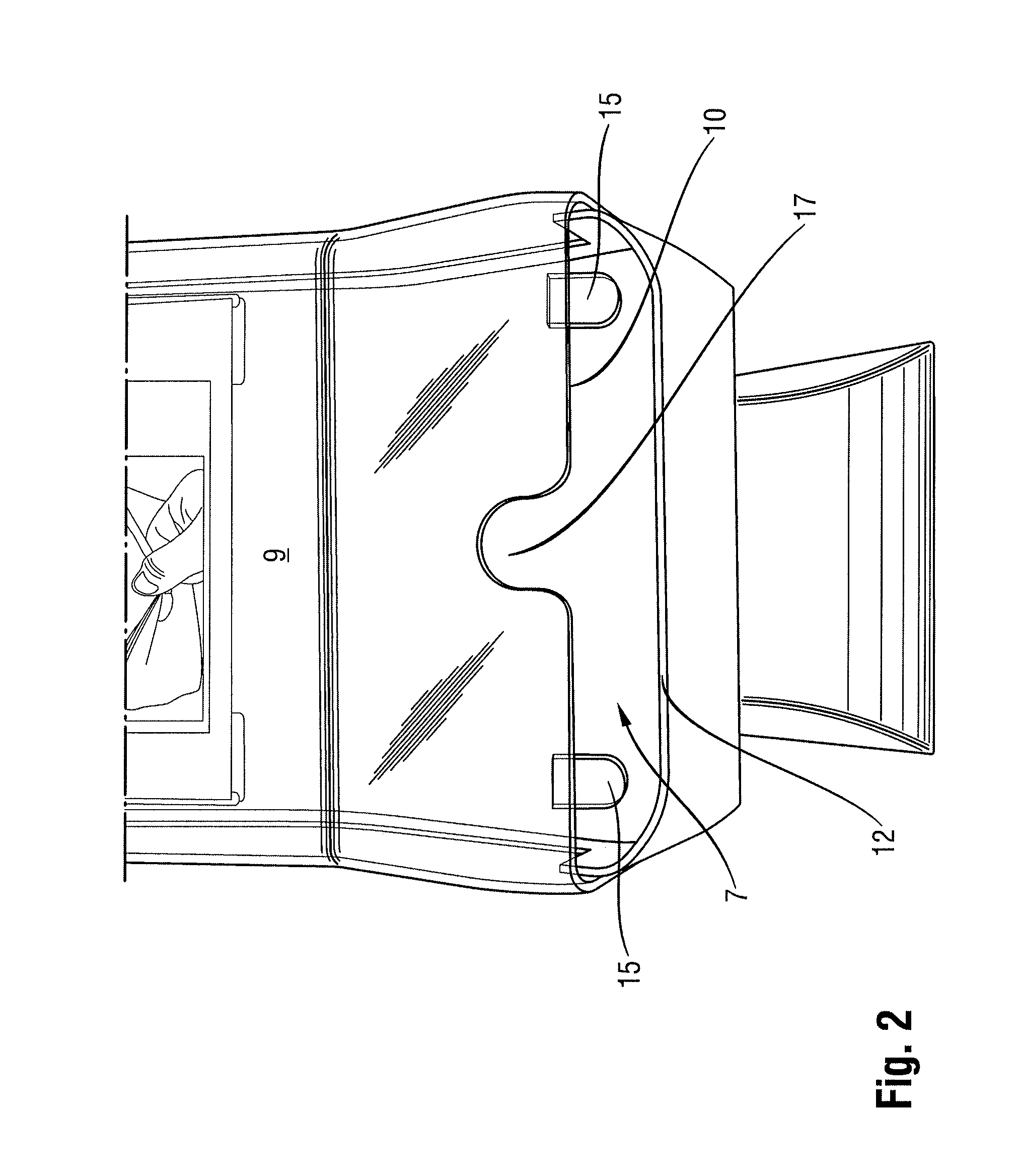
[0059]FIG. 2 shows the present invention in which the front wall 9 has been provided with first and second tabs 15 depending from the bottom edge 10 of the front wall 9 towards the bottom wall 11. The tabs 15 extend at least partially (preferably just partially) across the dispensing opening in a direction substantially normal to an inside surface of the bottom wall 11. The tabs 15 are provided for the purpose of interfering or blocking napkins from passing through the dispensing opening 7 in an upper part of the dispensing opening 7, and leaving a gap between a bottom of the tabs 15 and the bottom wall 11 to provide a lower portion of the dispensing opening 7 in which napkins are free to pass without interference from the tabs 15. The tabs 15 thus restrict an upper part of the dispensing opening and leave open a lower part of the dispensing opening 7.

[0060]The tabs 15 are provided on opposed sides of the dispensing opening 7 at positions inset from side ends of the dispensing openi...

second embodiment

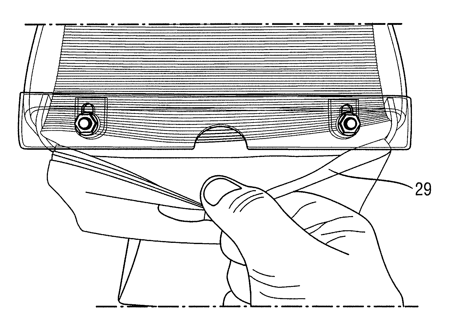
[0066]FIG. 4 shows an alternative modification of the dispenser 1 of FIG. 1 according to the present invention. A shield 20 is mounted to a bottom of the front wall 9 so as to depend from the front wall 9 and extend so that a bottom edge 26 of the shield 20 is in alignment with a front edge 12 of the bottom wall 11. The front edge 12 of the bottom wall 11 remains set back from an inside surface of a bottom of the shield 20 so as to provide a dispensing gap 25 therebetween. The shield 20 thus substantially blocks the dispensing opening 7 in a rear to front direction or in a direction in which a user would pull napkins directly out from the dispensing opening 7, which is a direction normal to the rear wall 13. Intuitively, one would, perhaps, consider this to negate multiple napkin dispensing per pull, but, in fact, the dispensing process, to be described below with respect to FIGS. 5a to 5c, allows multiple napkin dispensing per pull in a more controlled, metered manner.

[0067]The rel...

third embodiment

[0076]The adjustability of the position of the shield 20 provides the present invention. The adjustability may be increased beyond fine tuning using longer slots 27 so that the shield 20 may be moved into positions not aligning the bottom edge 26 of the shield 20 with the bottom wall 11, thereby providing an unblocked dispensing path in a lower portion of the dispensing opening 7. Also, the shield 20 can be removed by removing the nuts 30 and the bolts 23, which allows the configuration shown in FIG. 4 to be reverted to a configuration as shown in FIGS. 2 and 3. Yet further, the tabs 21 may be removable so that the configuration of FIG. 4 can be reverted to the conventional dispensing opening 7 shown in FIG. 1. This provides great flexibility in customizing the dispensing opening so as to suit particular applications.

[0077]Alternatively, the shield 20 should be formed as an integral part with the front wall 9, which sacrifices the adjustability feature, but allows alignment between ...


PUM


Abstract

A gravity feed dispenser including a dispensing opening that exposes part of a front face and part of a bottom face of a stack of interfolded napkins. Interference tabs restrict the dispensing opening at the front face of the stack of napkins. A stack of interfolded napkins is seated on a bottom wall of the dispenser. The bottom wall is set back from a front wall in a front to rear direction to provide a dispensing gap. A leading flap of the stack of napkins hangs through the dispensing gap while a leading fold of the stack of napkins is pressed against a bottom end of the front wall. When the leading flap is pushed back, the leading fold passes beneath a bottom edge of the front wall to be grasped by a user for dispensing napkins at least two at a time.

Description

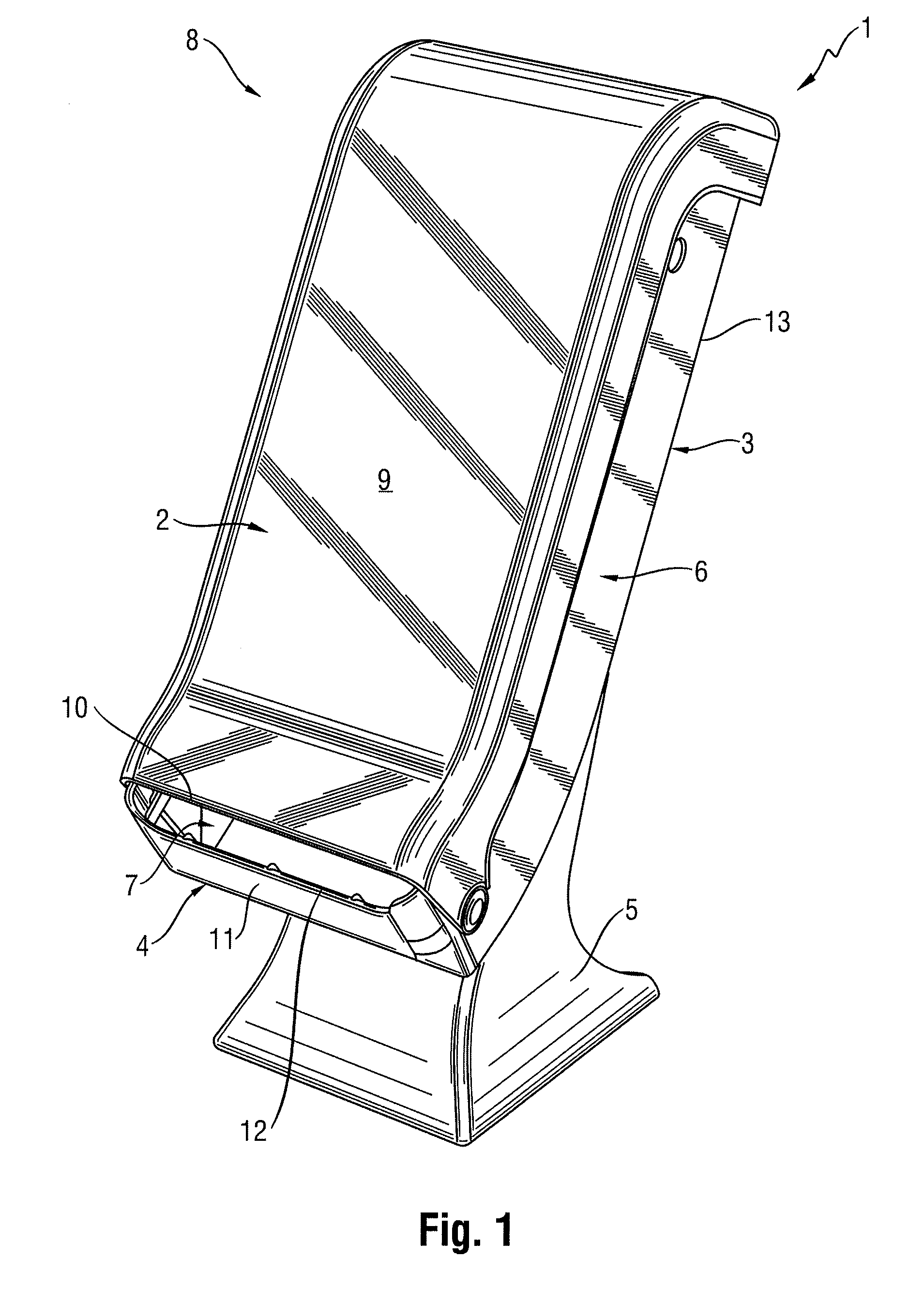
FIELD OF THE INVENTION[0001]The present invention is concerned with a gravity feed dispenser for containing a stack of interfolded sheet products such as napkins and the like and for dispensing the sheet products from a dispensing opening designed for dispensing more than one sheet product at a time.BACKGROUND TO THE INVENTION[0002]Gravity feed dispensers are known in the art, such as WO2005 / 034702 A1, U.S. Pat. No. 6,415,949 B1 and U.S. Pat. No. 6,334,544 B1. They are classified as gravity feed dispensers as they are designed so that, in use, the sheet products are delivered to the dispensing opening by force of gravity. This is distinct from other types of dispenser in which the sheet products are fed to the dispensing opening under the influence of a spring mechanism.[0003]In WO 2005 / 034702 A1, a gravity feed napkin dispenser is disclosed comprising a main body portion supported on a stand. A cover closes a front of the main body portion and is openable to permit reloading of a s...

Claims


Application Information

Patent Timeline
IPC IPC(8): A47K10/42
CPCA47K10/426A47K10/424
Inventor FORMON, JOHN S.
Owner SCA HYGIENE PROD AB
Learn More