
Locking structure of multifunctional stripping/cutting pliers

a multi-functional, locking technology, applied in the direction of electrical cables, cables removed/armoured, electrical cables, etc., can solve the problems of increased material cost of pliers, inconvenient spring assembly, bulky pliers in hand holding, etc., to achieve convenient assembly, convenient pressing operation, and easy locking arrangement

Inactive Publication Date: 2013-09-05
YANG SHYI DONG
View PDF7 Cites 14 Cited by
  • Summary
  • Abstract
  • Description
  • Claims
  • Application Information

AI Technical Summary

Benefits of technology

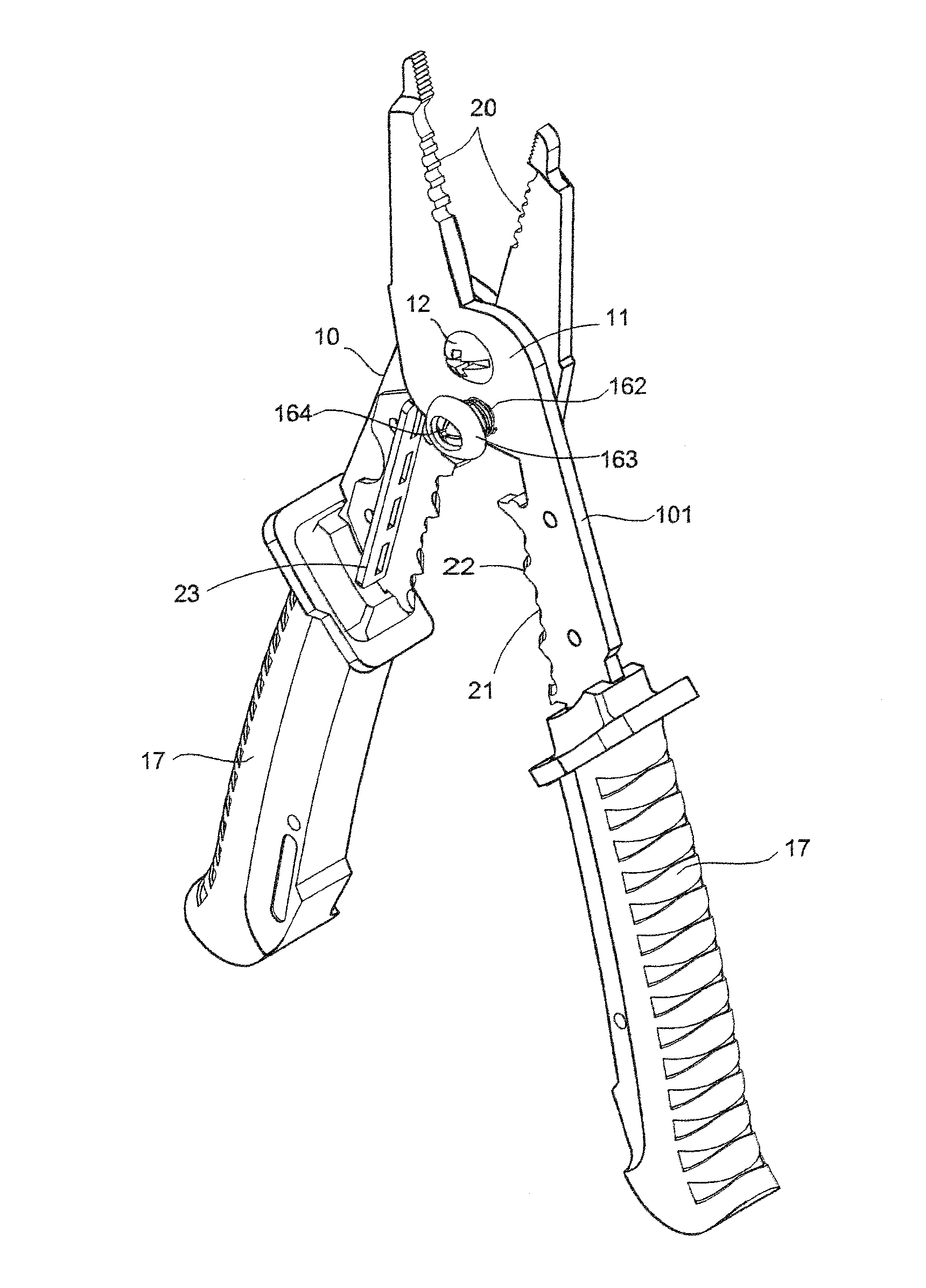
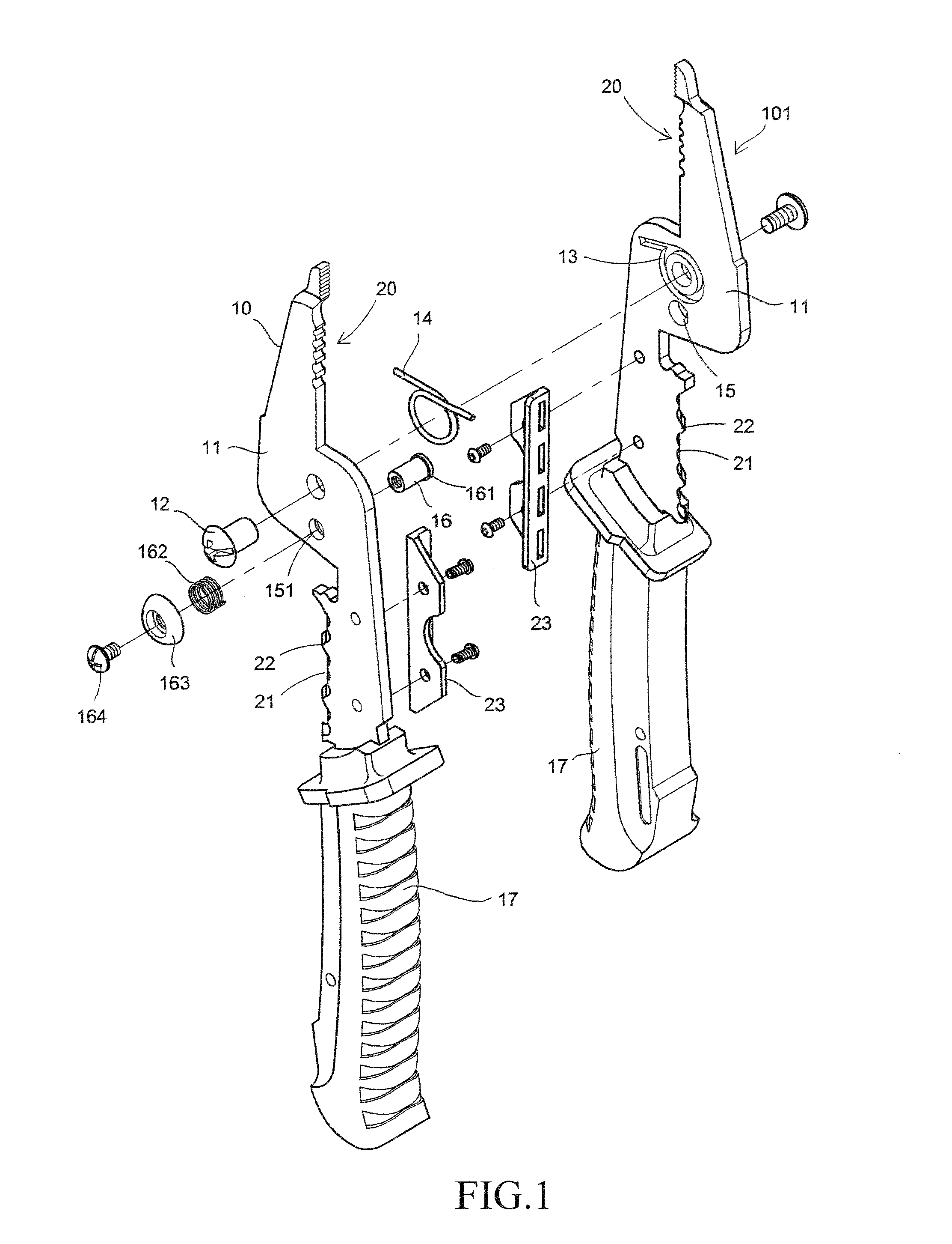
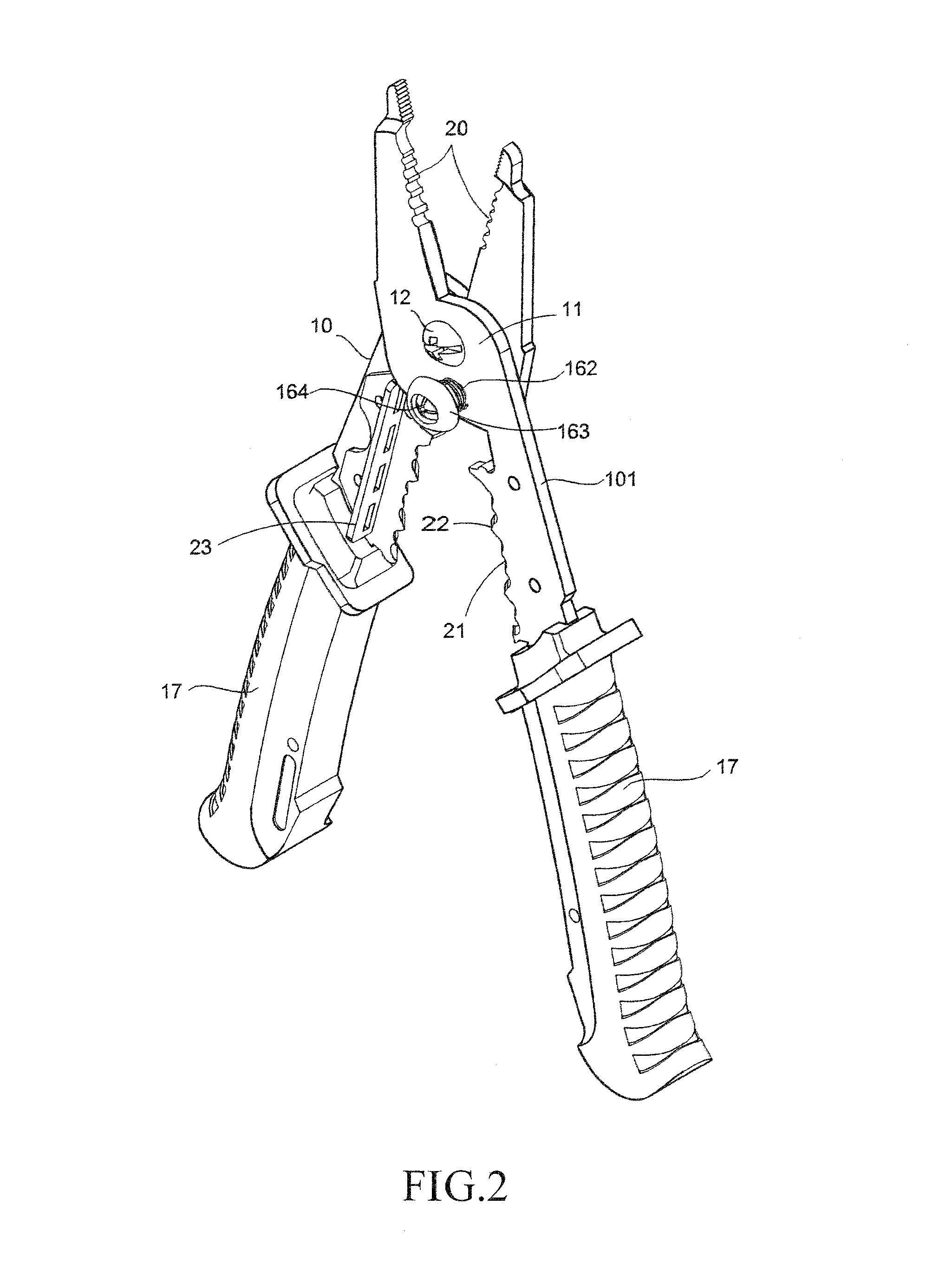
The present invention provides a locking structure for multifunctional stripping / cutting pliers, which includes a predetermined receiving slot in the pivot disks of the pliers to receive a spring for concealed arrangement and a hole with upper and lower segments to receive a positioning pin. This structure allows for easy pressing operation and secure cutting and storage of the pliers, effectively overcoming the problem of exposed control plate. The technical effects of this invention are improved safety and convenience in the cutting operations of the stripping / cutting pliers.

Problems solved by technology

Such a conventional structure of wire stripper is disadvantageous in cutting operation in that in the operation of the stripper, since the position-returning spring 35 is arranged below the central pivot pin 33, due to the need for proper positioning, the positioning projections must be made long and this causes inconvenience in assembling the spring 35.
Further, to accommodate the spring 35 to be assembled by being mounted outside, the pliers must be extended in length to provide an accommodation space and this increases the material cost of the pliers and makes the pliers bulky and heavy in hand holding, and what is more troublesome is that the spring 35 is often a coil spring and spacing between adjacent turns of the spring may inadvertently clamp a wire or a thin object therein and further, unexpected activation may cause an operator's hand to be accidently pinched and hurt.
This causes problems of safety of use and position returning by the spring.
Such a controlling operation is not convenient and it may often occur that the raised and irregular configuration may easily cause the raised control plate to contact and hook an object nearby or being accidently activated by an operator's hand, making the locking unexpected released, which leads to accident expansion of the pliers and thus a problem of safety may happen.

Method used


Image

  • Locking structure of multifunctional stripping/cutting pliers
  • Locking structure of multifunctional stripping/cutting pliers
  • Locking structure of multifunctional stripping/cutting pliers

Examples


Embodiment Construction

[0017]The following descriptions are exemplary embodiments only, and are not intended to limit the scope, applicability or configuration of the invention in any way. Rather, the following description provides a convenient illustration for implementing exemplary embodiments of the invention. Various changes to the described embodiments may be made in the function and arrangement of the elements described without departing from the scope of the invention as set forth in the appended claims.

[0018]The present invention provides multifunctional stripping / cutting pliers, of which an overall configuration shows an outside appearance similar to a conventional wire stripper but an improvement of the present invention over the conventional wire stripper is that a position-returning mechanism that is provided for facilitating the operation of the pliers is of a concealed arrangement and a locking mechanism that is provided for securing pliers mouth in a closed position when the pliers are clos...


PUM


Abstract

Multifunctional stripping / cutting pliers are provided for stripping and cutting multi-wire and multi-core electrical cable. The stripping / cutting pliers have plate like bodies that are pivoted in an opposing manner and form in pivot disks thereof a receiving slot in which a spring is received in a concealed arrangement. A stepped hole is provided to extend through a middle portion of the pivoted bodies at a lower side of the insertion site of the spring for receiving a positioning pin to extend therein so as to provide an easy depression operation from the outside of the bides to realize locking. Through the concealed and position-returning arrangement of the spring of the stripping / cutting pliers and assisted by simple depression that achieves locking, the cutting operation of the stripping / cutting pliers can provides the effects of being easy, being practical, and operation and locking safety.

Description

(A) TECHNICAL FIELD OF THE INVENTION[0001]The present invention generally relates to an improvement of locking structure of multifunctional stripping / cutting pliers, in which a predetermined receiving slot is formed in opposing surfaces of pivot disks of cutting bodies that are provided for wire stripping and cutting for receiving therein a position returning spring in a concealed arrangement and the pivot disks form, in a middle portion of the pivot disks below the portion where the spring is arranged, a through hole that have upper and lower segments of different diameter to receive a positioning pin to insert therein in such a way that a large-diameter hole formed in the lower segment of the stepped hole configuration receive therein a bottom end of the positioning pin that has an expanded diameter for easy operation of locking, allowing the cutting operation and storage of the stripping / cutting pliers to achieve the operation purposes of wire stripping and cutting that are easy ...

Claims


Application Information

Patent Timeline
Patent Type & Authority Applications(United States)
IPC IPC(8): H02G1/12
CPCH02G1/1214H02G1/005
Inventor YANG, SHYI-DONG
Owner YANG SHYI DONG
Learn More