
Battery pack

a battery pack and battery technology, applied in the field of batteries, can solve the problems of leakage of electricity, which is achieves the effects of preventing the leakage of electricity charged in battery cells, reducing the number of drain holes, and efficient draining water

Active Publication Date: 2013-08-29
MAKITA CORP
View PDF6 Cites 31 Cited by
  • Summary
  • Abstract
  • Description
  • Claims
  • Application Information

AI Technical Summary

Benefits of technology

The battery packs described in these patents have the technical effects of efficiently draining water, preventing leakage of electricity, minimizing the number of drain holes, preventing short circuits, easily guiding water drainage, improving drainage performance, and preventing electrical connection between terminal members. These effects can maintain the battery pack's performance and keep it clean.

Problems solved by technology

Therefore, water such as raindrops may be splashed on such a battery pack, so that water may enter into the housing case.
Here, when water enters into the housing case to cause the above-mentioned lead plates to be soaked in the water, unintended lead plates may be electrically connected to each other to the result that electricity, which is charged in battery cells, leaks.
However, if the plurality of drain holes are merely formed at the bottom portion of the housing case, conversely, water or dust may easily enter into the housing case from the drain holes.

Method used


Image

  • Battery pack
  • Battery pack
  • Battery pack

Examples


first embodiment

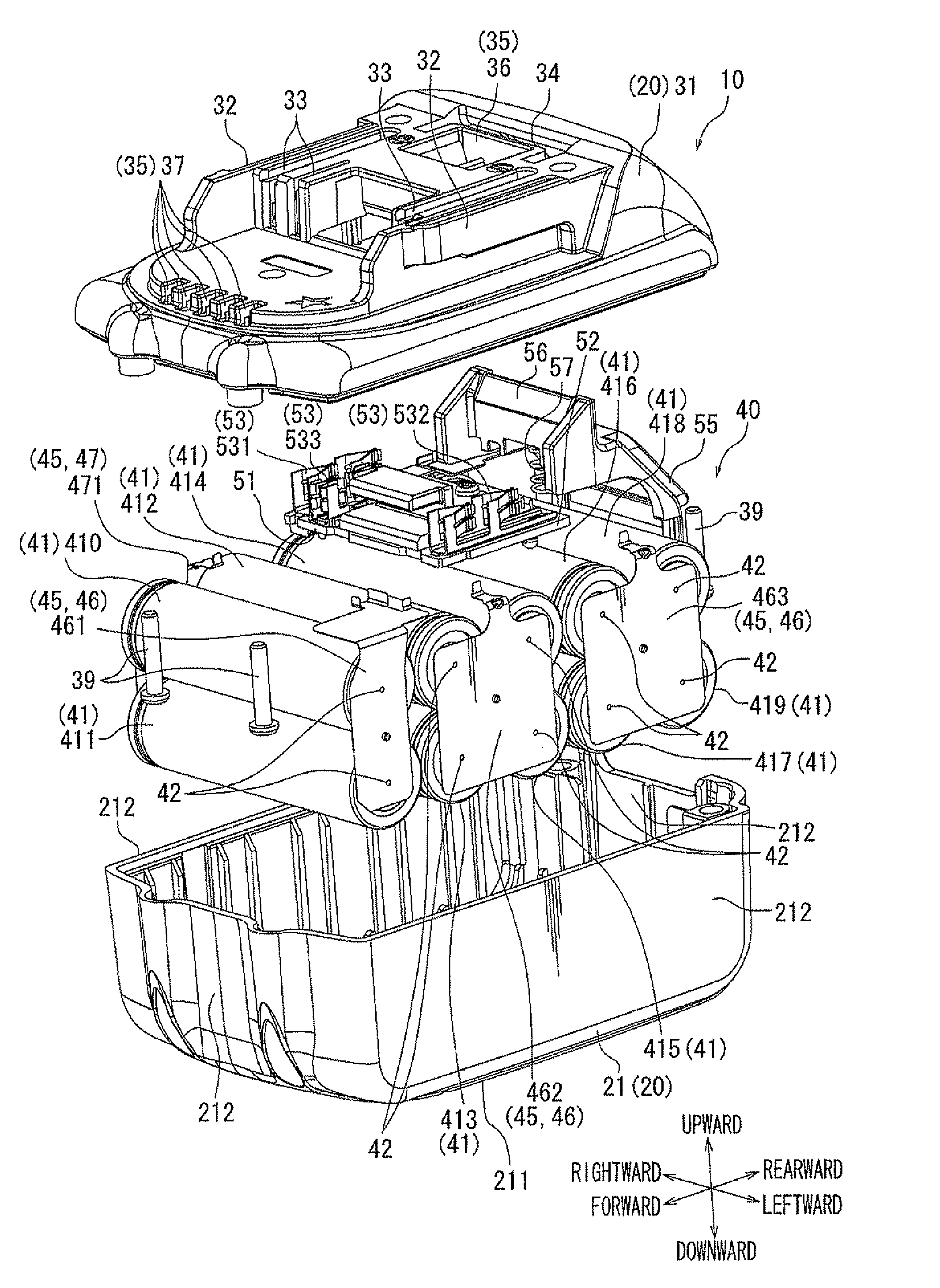
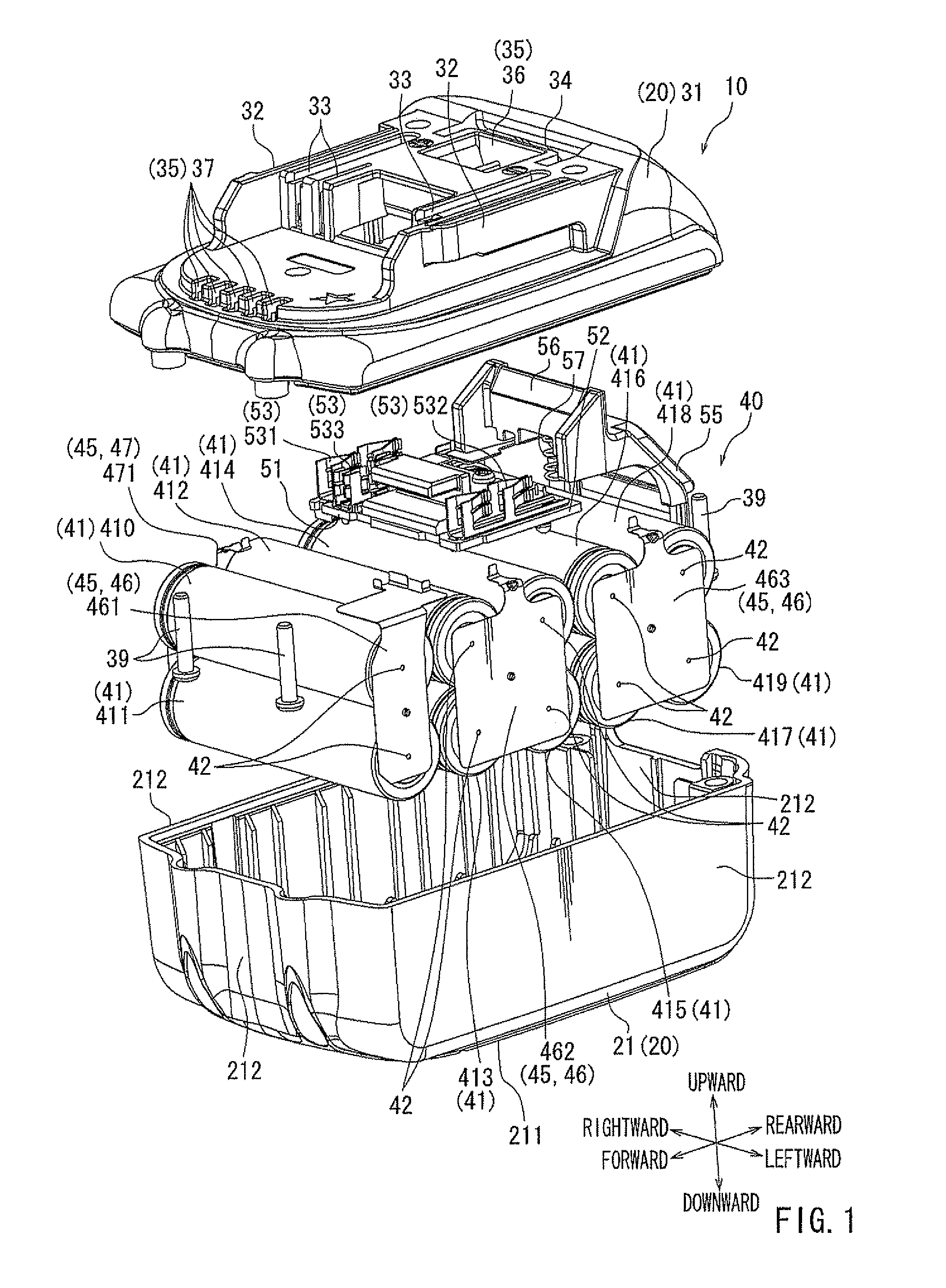
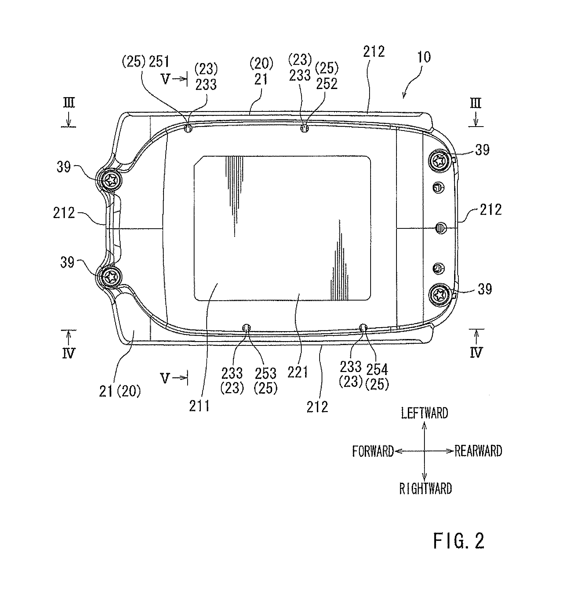
[0078]The first embodiment, which embodies a battery pack according to the invention, will be described below with reference to FIGS. 1 to 10.

[0079]An exploded perspective view of FIG. 1 shows a battery pack 10 of a first embodiment that is embodied in a first example. This exploded perspective view shows the battery pack 10 so that the inside of a battery pack body 40 is seen. Meanwhile, in the following description, an electrical connection side of the battery pack 10 will be defined as the upper side and a slide mounting direction of the battery pack 10 will be defined as a forward direction.

[0080]The battery pack 10 is configured to be detachably mounted by sliding onto a tool body (mounting target) of an electric tool that is typified by, for example, an electric screwdriver. The battery pack 10 serves as a drive power source of the tool body having on the battery pack 10 mounted thereon. For this reason, when the charge amount of the battery pack 10 is reduced, the battery pac...

second embodiment

[0124]Next, the second embodiment, which embodies the battery pack according to the invention, will be described with reference to FIGS. 11 and 12. Here, a perspective view of FIG. 11 is a perspective view of a case body 21B that is viewed in perspective so that the inside of the case body is seen. Further, a cross-sectional view of FIG. 12 is a cross-sectional view of the case body 21 B of FIG. 11 taken along line XII-XII.

[0125]That is, although the entire view is not shown, the battery pack of the second embodiment is different from the battery pack 10 of the above-mentioned first embodiment only in the structure of the case body 21. That is, in the battery pack of the second embodiment, a part of the structure of a drain passage 27B as a flow guide device is set to be present between the lead plates 45; a drain hole 25B is set to a position different from the position between the lead plates 45 unlike in the modification of the above-mentioned first embodiment.

[0126]The second em...

second example

[0131]Next, third and fourth embodiments, which are embodied in a second example shown in FIGS. 13 to 21, will be described.


PUM

PropertyMeasurementUnit
diameteraaaaaaaaaa
electrical potentialsaaaaaaaaaa
poweraaaaaaaaaa

Abstract

A battery pack may include a drainage device provided at a bottom portion of the housing case. The drainage device may include a drain hole communicating between the inside and the outside of the housing case, so that water introduced into the housing case is discharged to the outside of the housing case. The drainage device may be disposed between two of the terminal members that are connected to electrodes of the battery cells.

Description

TECHNICAL FIELD[0001]Embodiments of the present invention relates to a battery pack configured to be capable of being mounted to a tool body of an electric tool as a power source of the electric tool.BACKGROUND ART[0002]In the related art, an electric tool includes a tool body driven by electric power, and a battery pack that serves as a power source for the tool body. The battery pack is configured to be detachably mounted to the tool body. The battery pack includes a housing case that forms an exterior cover, and a battery body that is installed in the housing case. The battery body includes a plurality of battery cells that can be charged and discharged, and a control board that controls the charge and discharge operations. Lead plates are connected to electrodes of the plurality of battery cells so that the battery cells are electrically connected in series or in parallel to each other.[0003]Meanwhile, there may be an occasion that the afore-mentioned electric tool is used outdo...

Claims


Application Information

Patent Timeline
Patent Type & Authority Applications(United States)
IPC IPC(8): H01M2/10H01M50/213H01M50/244H01M50/296H01M50/60
CPCH01M2/1055H01M2/1016H01M2/204Y02E60/10H01M50/213H01M50/24H01M50/691H01M50/296H01M50/60H01M50/244H01M2220/30
Inventor HAYASHI, HIDEKAZUKONDO, EIJIOGURA, HIRONORITAGA, HIDEYUKIOGINO, KAZUTOSHI
Owner MAKITA CORP
Learn More