
Turning bearing with separator

a technology of turning bearings and separators, which is applied in the direction of bearings, shafts and bearings, rotary machine parts, etc., can solve the problems of requiring much time and effort in the assembly of bearings, and achieve the effects of reducing frictional resistance, facilitating installation, and facilitating lubricant flow

Active Publication Date: 2013-08-29
NIPPON THOMPSON
View PDF5 Cites 5 Cited by
  • Summary
  • Abstract
  • Description
  • Claims
  • Application Information

AI Technical Summary

Benefits of technology

The present invention aims to provide a turning bearing with a separator that can be used in cross-roller turning bearings, where the adjacent rollers tilt alternately in opposite directions to each other in a way that their axes intersect at right angles. The separator is designed to fit over the roller's surface with concave surfaces that combine in a crisscrossed relation, allowing for easy installation in a raceway. The separator can be installed in either the outer or inner ring of the bearing through a loading hole, ensuring high performance in assembly work even with small rollers. Additionally, the separator has a sufficient thickness to make contact with the roller at the same position, and the raised tops on the leading and trailing sides of the separator are made flat for improved performance.

Problems solved by technology

This work poses a problem of requiring much time and effort on assemblage of the bearing.

Method used


Image

  • Turning bearing with separator
  • Turning bearing with separator
  • Turning bearing with separator

Examples


Embodiment Construction

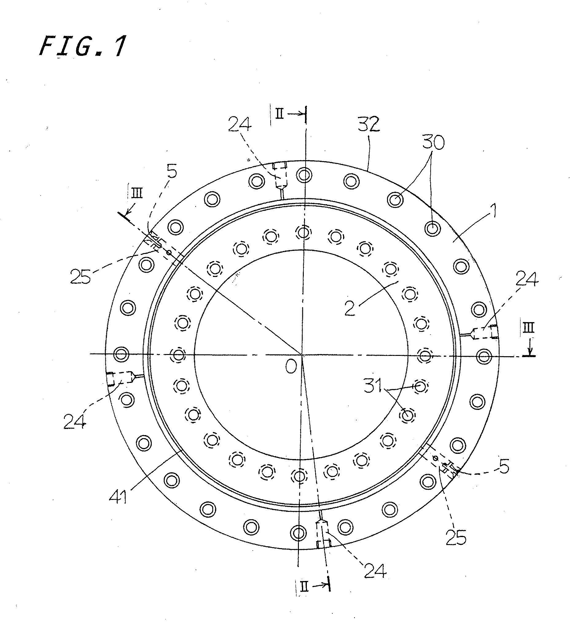
[0030]The turning bearing equipped with a separator constructed according to the present invention will find extensive applications in relative turning, rocking and turning systems used in a diversity of machinery including semiconductor fabricating equipments, precision machines, measurement / inspection equipments, medical appliances, industrial robots, various assembling machines, transportation machines, machine tools, micromachines and so on. A preferred first embodiment of the turning bearing of the present invention will be explained in detail with reference to the accompanying drawings. Referring to FIGS. 1 to 4, the turning bearing of the present invention is in general composed of an outer ring 1, inner ring 2, and rollers 3 and separators 4 (see FIG. 5) lying in raceways 10 defined between the outer ring 1 and the inner ring 2, the separators 3 being disposed between the rollers adjoining each other. The turning bearing is a double-row angular-contact roller bearing in whic...


PUM


Abstract

The turning bearing has a separator whose leading and trailing sides are concaved to fit over circular rolling surfaces of the rollers to provide concavities where concaved surfaces lying either in parallel with and in perpendicular to the axis of the roller. The rollers fit in the separator in either of two different directions. The separator can be easier installed into the raceway through a loading hole without the posture of the separator in mind. The separator has a quadrilateral in a transverse cross-section perpendicular to a traveling direction of the separator of which a peripheral surface is in opposition to the outer ring and the inner ring. The separator has a center through-hole. The concaved surfaces in the separator are contoured in arced or curved profiles and bulge gradually closer to a circular edge of the through-hole to form arcing bulges at bottoms of the curved surfaces.

Description

FIELD OF THE INVENTION[0001]The present invention relates to a turning bearing or swivel bearing suitable for use in a turning or pivotal component installed in, for example a variety of assembling machines, machine tools, industrial robots, semiconductor fabricating equipment.BACKGROUND OF THE INVENTION[0002]An international publication No. WO 2009 / 020087 discloses an example of the double-row roller bearing, which is composed of an outer ring whose inside circular surface has two rows of outside grooved tracks, or races, extending circumferentially of the outer ring, an inner ring whose inside circular surface has two rows of inside grooved races extending circumferentially of the inner ring in opposition to the outside grooved races of the outer ring to define raceways between the outside grooved races and inside grooved races, and a plurality of rollers lying in the raceways so as to circulate through the raceways with carrying loads as the inner ring and the outer ring rotate r...

Claims


Application Information

Patent Timeline
Patent Type & Authority Applications(United States)
IPC IPC(8): F16C33/30
CPCF16C33/30F16C43/06F16C2240/30F16C19/40F16C33/3706F16C19/38F16C2300/02F16C2240/40
Inventor KIKUCHI, SHUNSUKE
Owner NIPPON THOMPSON
Learn More