
Gate

a technology for securing gates and equipment, applied in the direction of hinges, door/window fittings, wing accessories, etc., can solve the problems of exhibiting different dimensions, leaving gaps in the system or equipment, and gate use typically cannot cover gaps exhibiting different dimensions

Active Publication Date: 2013-08-29
SAFERACK
View PDF48 Cites 14 Cited by
  • Summary
  • Abstract
  • Description
  • Claims
  • Application Information

AI Technical Summary

Benefits of technology

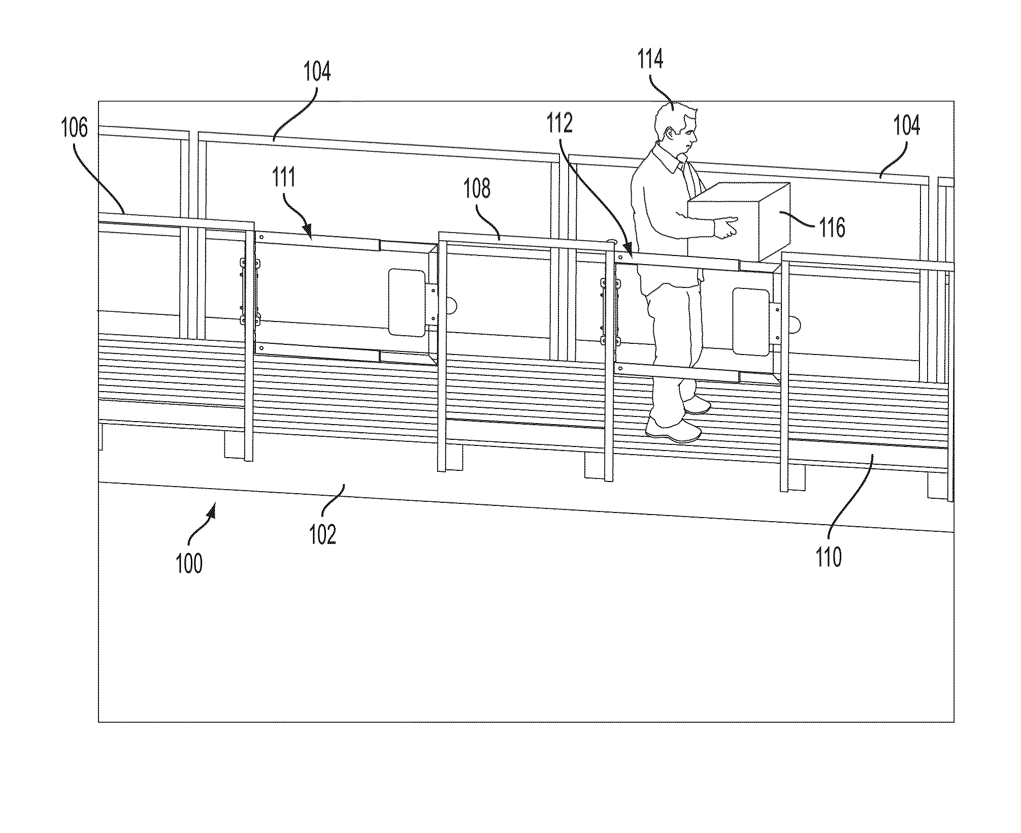
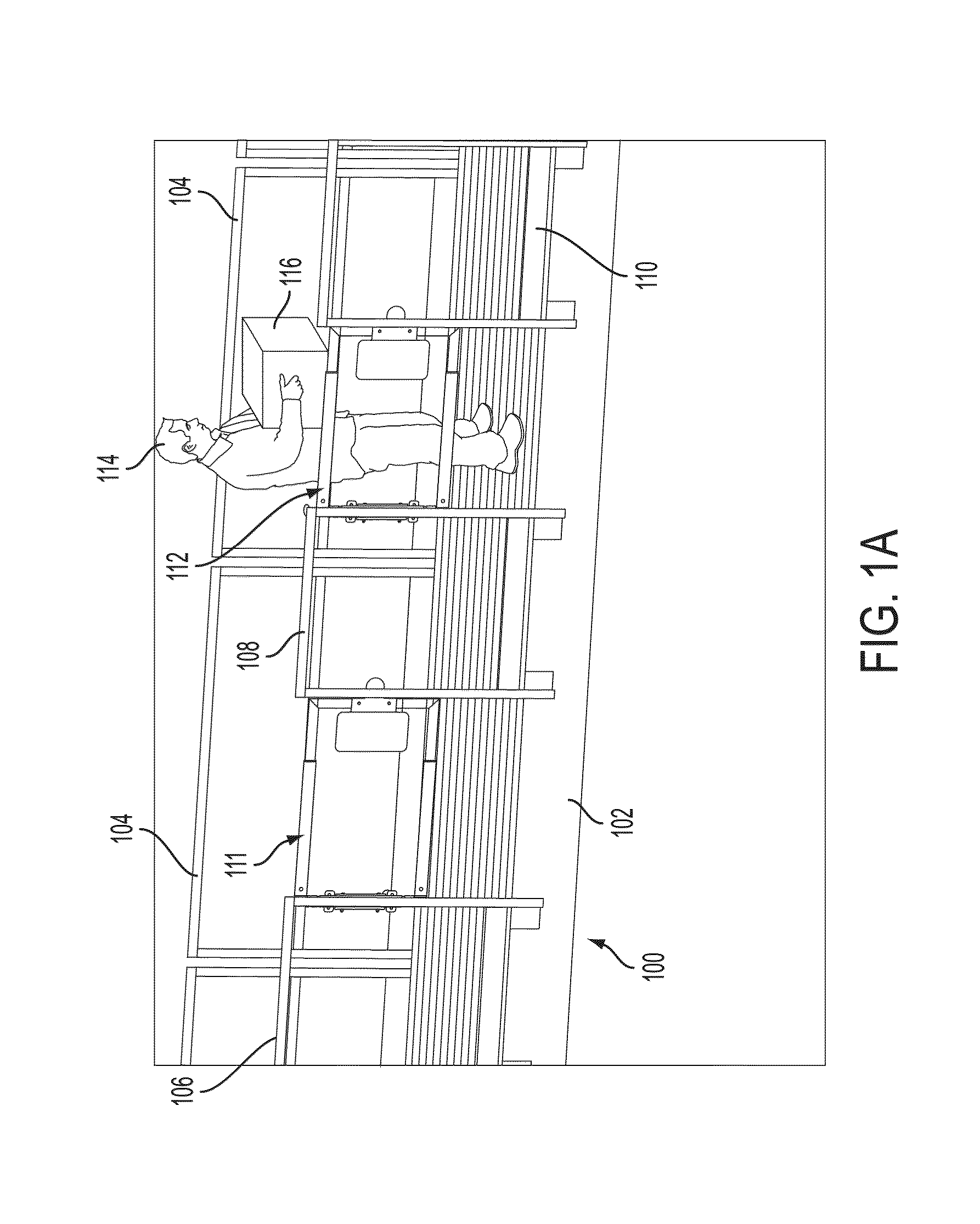
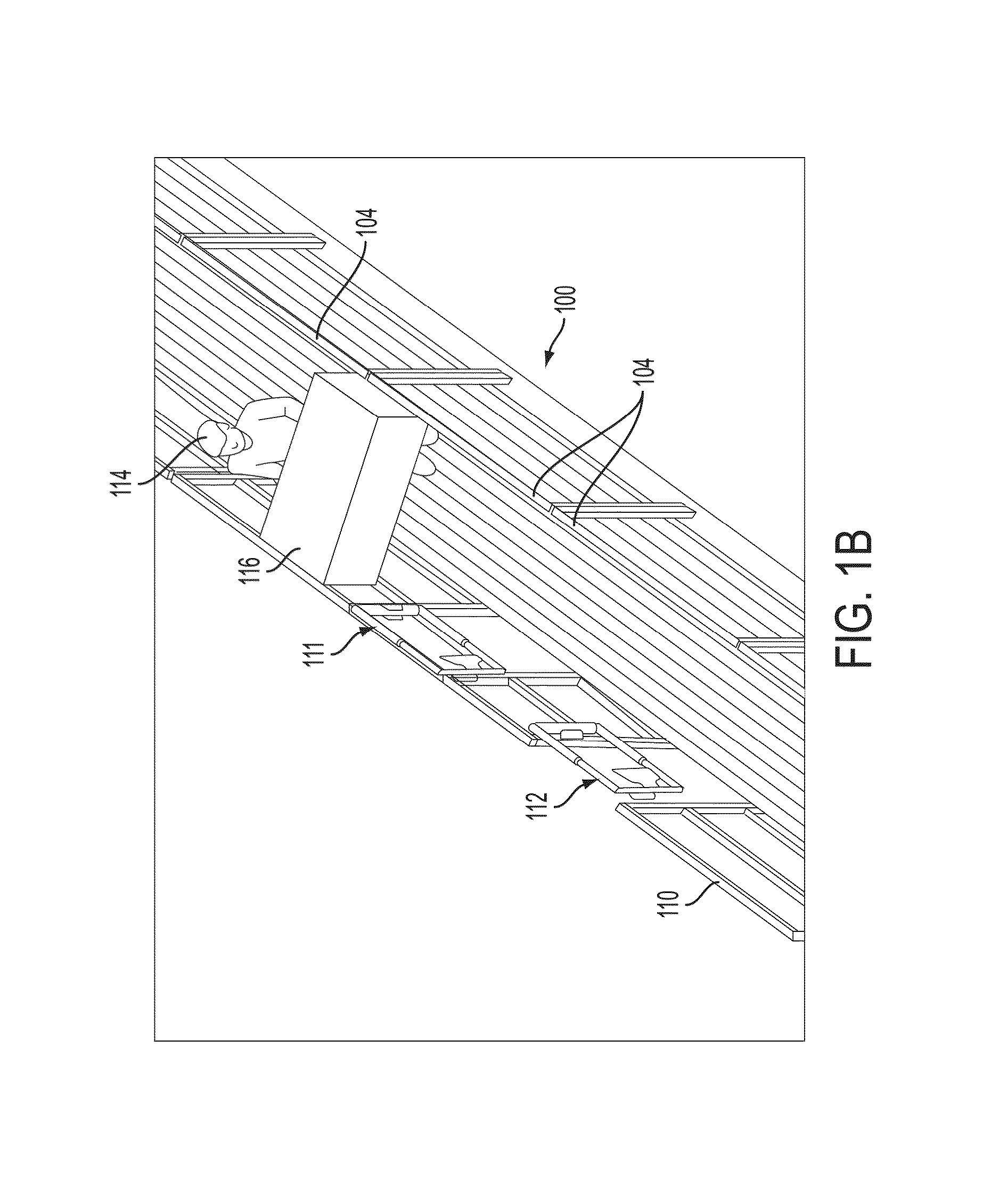
The present invention provides an adjustable gate that includes a pair of supporting arms with interior cavities and an adjustable arm that can be inserted into the supporting arms. The adjustable arm has an adjustable system to change its length, which can be locked into place relative to the supporting arms using a rubber compression member or a pin. The gate can also be fixed relative to the first supporting arm using an adjustable compression member and a compressing fitting. The technical effect of the invention is an adjustable gate with improved flexibility and stability, which can be easily and securely locked into place relative to the supporting arms.

Problems solved by technology

The access points along the platform system or along other portions of fall restraint equipment may provide access to desired locations, such as the top of a railroad carriage, but typically leave a gap in the system or equipment when not in use.
Once manufactured, the gate typically cannot be used to cover a gap exhibiting different dimensions.

Method used


Image

  • Gate
  • Gate
  • Gate

Examples


Embodiment Construction

[0025]Reference will now be made in detail to presently preferred embodiments of the invention, one or more examples of which are illustrated in the accompanying drawings. Each example is provided by way of explanation of the invention, not limitation of the invention. In fact, it will be apparent to those skilled in the art that modifications and variations can be made in the present invention without departing from the scope or spirit thereof. For instance, features illustrated or described as part of one embodiment may be used on another embodiment to yield a still further embodiment. Thus, it is intended that the present invention covers such modifications and variations as come within the scope of the appended claims and their equivalents.

[0026]Aspects of the present invention are related to fall restraint equipment. Examples of fall restraint equipment and the components thereof are set forth in copending U.S. patent application Ser. Nos. 12 / 329,883 (entitled “A Gangway and Me...


PUM


Abstract

A gate may include a first supporting arm and an adjustable arm. The first supporting arm may include an interior surface and an interior cavity. The adjustable arm may include an insertable end, an adjustable compression member and a compression fitting. The insertable end may be configured to be inserted into the interior cavity of the first supporting arm. The adjustable compression member may be disposed at the insertable end. The compressing fitting may be configured to adjust the adjustable compression member. When the insertable end is inserted into the interior cavity of the first supporting arm, the adjustable compression member is adjusted to compress against the interior surface so that the adjustable arm is fixed relative to the first supporting arm.

Description

CROSS REFERENCE TO RELATED APPLICATIONS[0001]This application claims the benefit of priority to U.S. Provisional Patent Application No. 61 / 599,276 filed on Feb. 15, 2012 and which is incorporated herein by its entirety.FIELD[0002]Embodiments of the present invention relates to fall restraint equipment, and, more particularly, to a swing gate for fall restraint equipment.BACKGROUND OF THE INVENTION[0003]Fall restraint equipment may include platforms, ramps, bridges, steps, guardrails, gangways, cages, gates, and other support structures. Gangways, for instance, may be used to provide access to an area, such as the top of a storage container. For example, a semi-trailer truck or a railroad carriage transporting dry goods may need to be unloaded from the container's top. A gangway is used to provide workers a path to unload the material. Additionally, an articulating cage may be lowered from the gangway or, alternatively, from a support structure in order to encase the area from which ...

Claims


Application Information

Patent Timeline
Patent Type & Authority Applications(United States)
IPC IPC(8): E06B11/04
CPCE06B11/00E06B11/045E05D7/0009E05F1/1207E06B11/022E06B11/04E05F1/12E05Y2900/40E06B3/921
Inventor HONEYCUTT, ROBERT W.JONES, CARSON ALLAN
Owner SAFERACK
Learn More