
Particle size breakup apparatus

a technology of particle size and apparatus, which is applied in the field of rotational rotorstators, can solve the problems of not being useful enough to estimate, not being practical in the actual production site, and not being useful enough to achieve the effect of good flavor, taste, physical properties and qualities

Active Publication Date: 2013-08-22
MEIJI CO LTD
View PDF25 Cites 12 Cited by
  • Summary
  • Abstract
  • Description
  • Claims
  • Application Information

AI Technical Summary

Benefits of technology

The present invention provides a mixer of the rotor-stator type with improved performance by changing the shear stress or flow rate of the liquid being processed. It also provides a comprehensive performance estimation method that can be applied to different mixer configurations and liquid circulation modes for designing the higher performance mixer. Additionally, the manufacturing method allows for the production of foods, pharmaceutical medicines, and chemical products using the higher performance mixer.

Problems solved by technology

This, however, is not practical in the actual production sites and is of no utility.
Specifically, there are no reports regarding the study cases in which the processing (agitation and mixing) time of the mixer is the object for consideration, and those study cases are not useful enough to estimate the resulting drop diameters that can be obtained during the particular mixer running period.
In most cases, however, those indices can only be applied to each of the individual mixers having the same configuration.
In the actual cases, however, they cannot be applied to the mixers of the various types having the different configurations.
That is, there are no indices that can be applied to the mixers having all possible configurations.
There are also no study cases in which those methods can be applied to the mixers of the various types having the different configurations, and the data on the results obtained by the experiments on such study cases have not been arranged or organized systematically into the graphical chart.
More specifically, in the prior art, there is no estimation method that can be used to estimate the resulting drop diameters that would be obtained by using the large-scale devices (actual production installation) for the mixers of the various types and permitting such large-scale devices to run during the particular time period, or there is no estimation method that can be used to estimate the particular resulting drop diameters obtained during the particular running time or the processing or agitating time required until such particular resulting drop diameters can be obtained.

Method used


Image

  • Particle size breakup apparatus
  • Particle size breakup apparatus
  • Particle size breakup apparatus

Examples


embodiments

[0213]Several preferred embodiments of the present invention and some of the examples thereof will now be described with the particular reference to the accompanying drawings. It should be understood that the present invention is not restricted to those embodiments and examples, but the preferred embodiments may be modified in numerous ways without departing from the technical scope defined in the appended claims.

[0214]Now, the high performance mixer will be described in general terms by using FIGS. 15 to 19, wherein the total energy dissipation rate E a that may be derived from the Equation 1 as proposed by the present invention is may be used as the index, the performance estimation may be made by using the value εa as the index, the high-performance mixer's configuration may be defined by the verification results of the performance estimation, and the high-performance mixer may be designed on the basis of that definition.

[0215]The mixer of the rotor-stator type as proposed by the...


PUM


Abstract

A mixer of the rotor-stator type that includes a stator having a plurality of openings and a rotor disposed on the inner side of the stator and spaced by a predetermined gap away from the stator is described, wherein the mixer that is capable of improving the shearing stress applied upon the liquid being processed and provides the higher performance is proposed, more specifically, the mixer that allows the shearing stress applied upon the liquid being processed to be changed and adjusted accordingly or allows the flow rate in which the liquid being processed flows to be changed and adjusted accordingly is proposed.The stator includes a plurality of stators each having a different circumferential diameter, and the rotor is disposed on the inner side of the plurality of stators and spaced by the predetermined gap away from the stators so that the stators and the rotor can be brought closer to or farther away from each other in the direction in which the rotary shaft of the rotor extends

Description

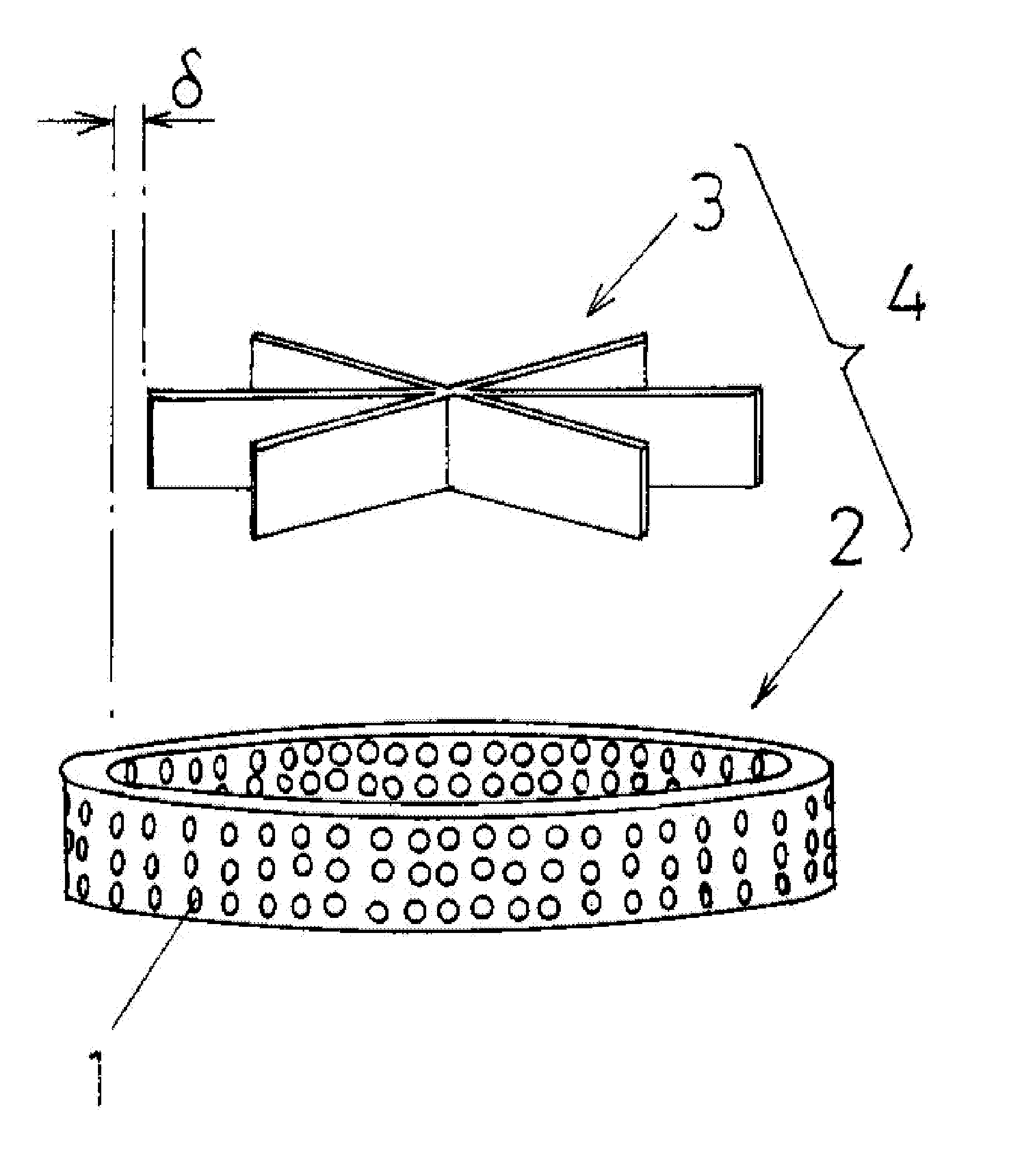
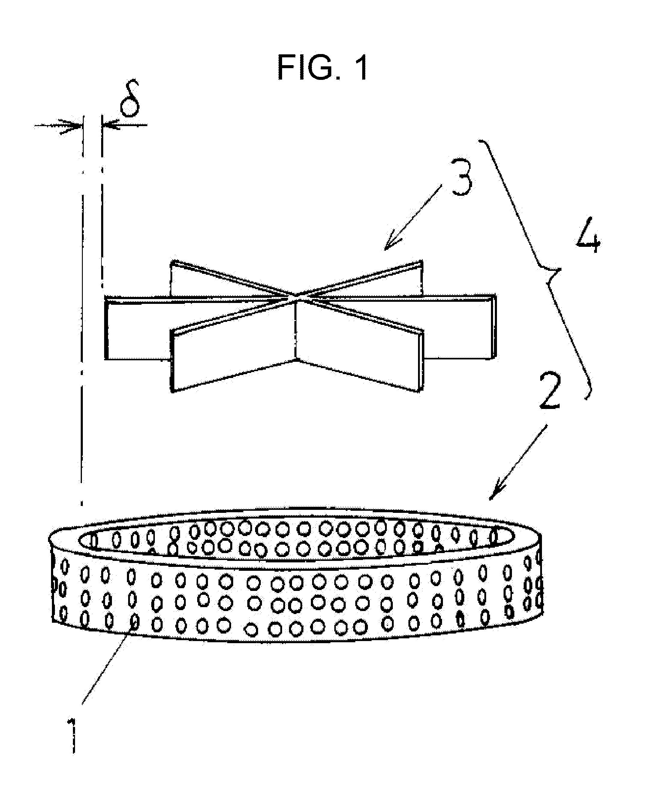
BACKGROUND[0001]1. Technical Field[0002]The present invention relates to the mixers of the so-called rotor-stator type, and more specifically to the mixer that includes a stator having a plurality of openings (holes) and a rotor that is disposed on the inner side of the stator and spaced by a particular gap away from the stator.[0003]2. Description of the Prior Art[0004]As shown in FIG. 1, it is general that the mixer of the so-called rotor-stator type comprises a mixer unit 4 that includes a stator 2 having a plurality of openings (holes) 1 and a rotor 3 disposed on the inner side of the stator 2 and spaced by a particular gap δ from the stator 2. Such mixer of the rotor-stator type is provided for subjecting a fluid or fluid or liquid being processed to the emulsification, dispersion, particle size breakup, mixing or any other similar process, by taking advantage of the fact that a high shear stress may be produced in the neighborhood of the gap between the stator 3 capable of rot...

Claims


Application Information

Patent Timeline
Patent Type & Authority Applications(United States)
IPC IPC(8): B01F7/00
CPCB01F5/10B01F7/164B01F7/00016B01F2215/0409B01F2215/0404B01F25/50B01F27/812B01F27/051B01F27/2721B01F27/2724
Inventor KAMIYA, TETSU
Owner MEIJI CO LTD
Learn More