
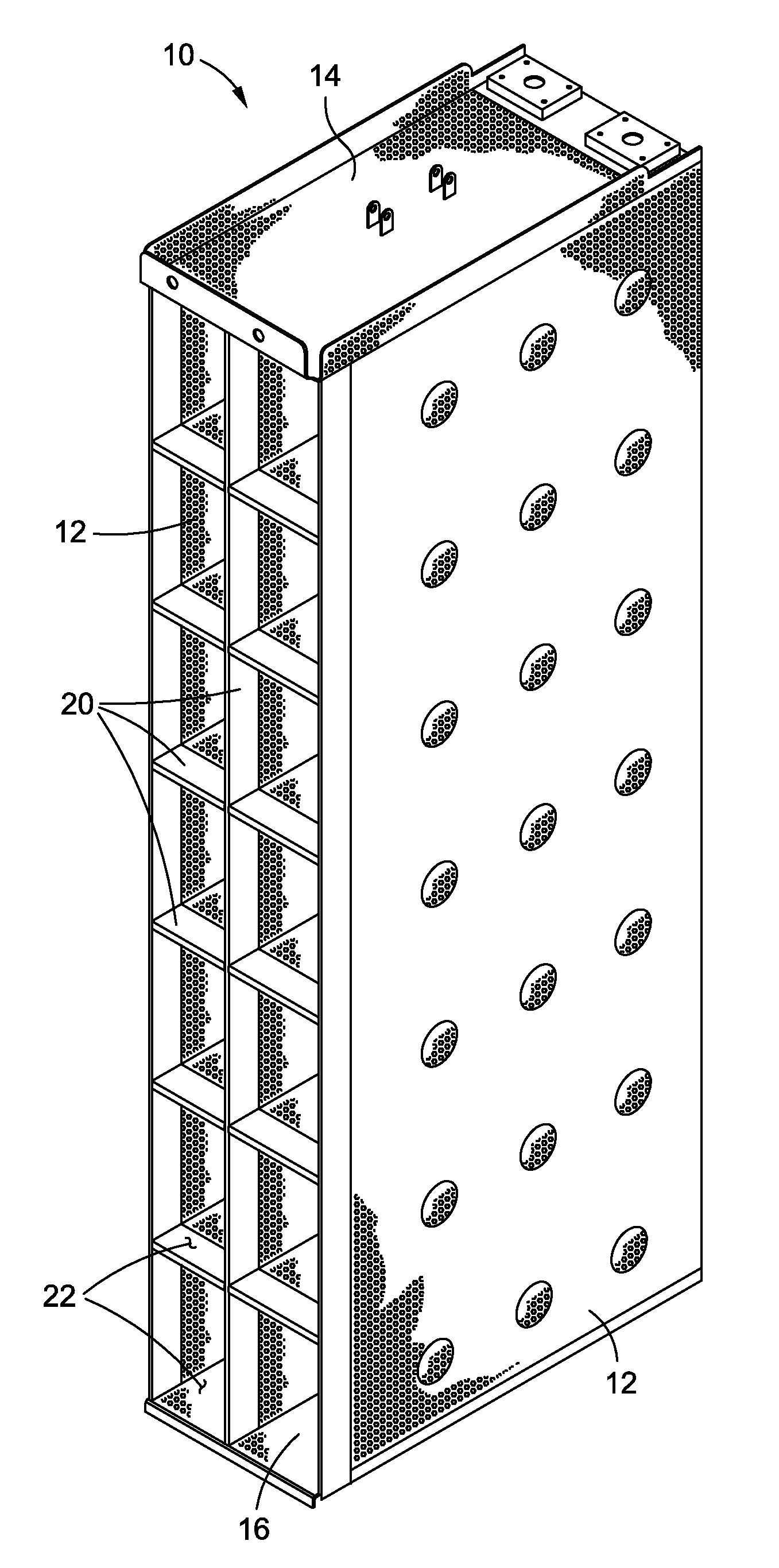
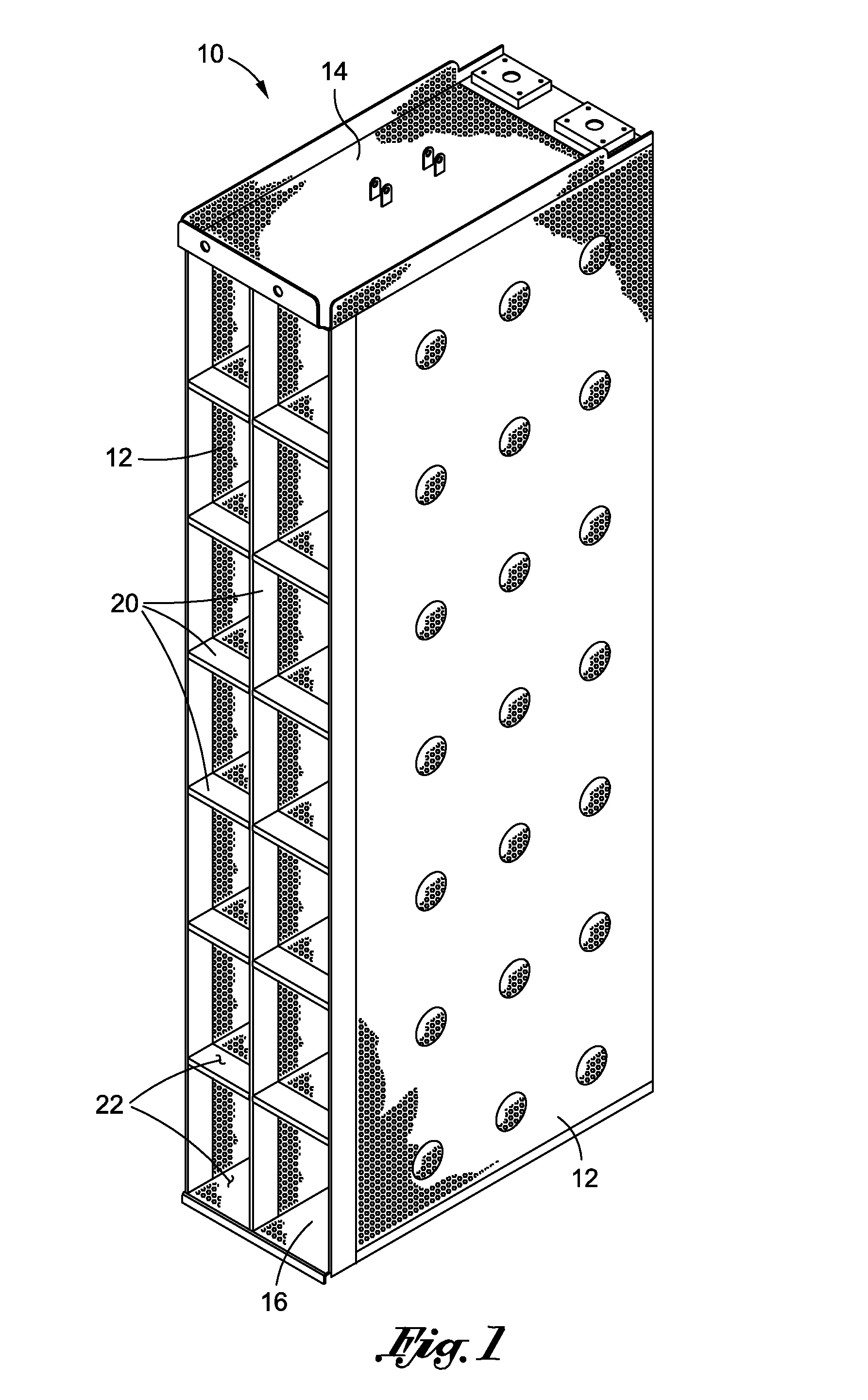
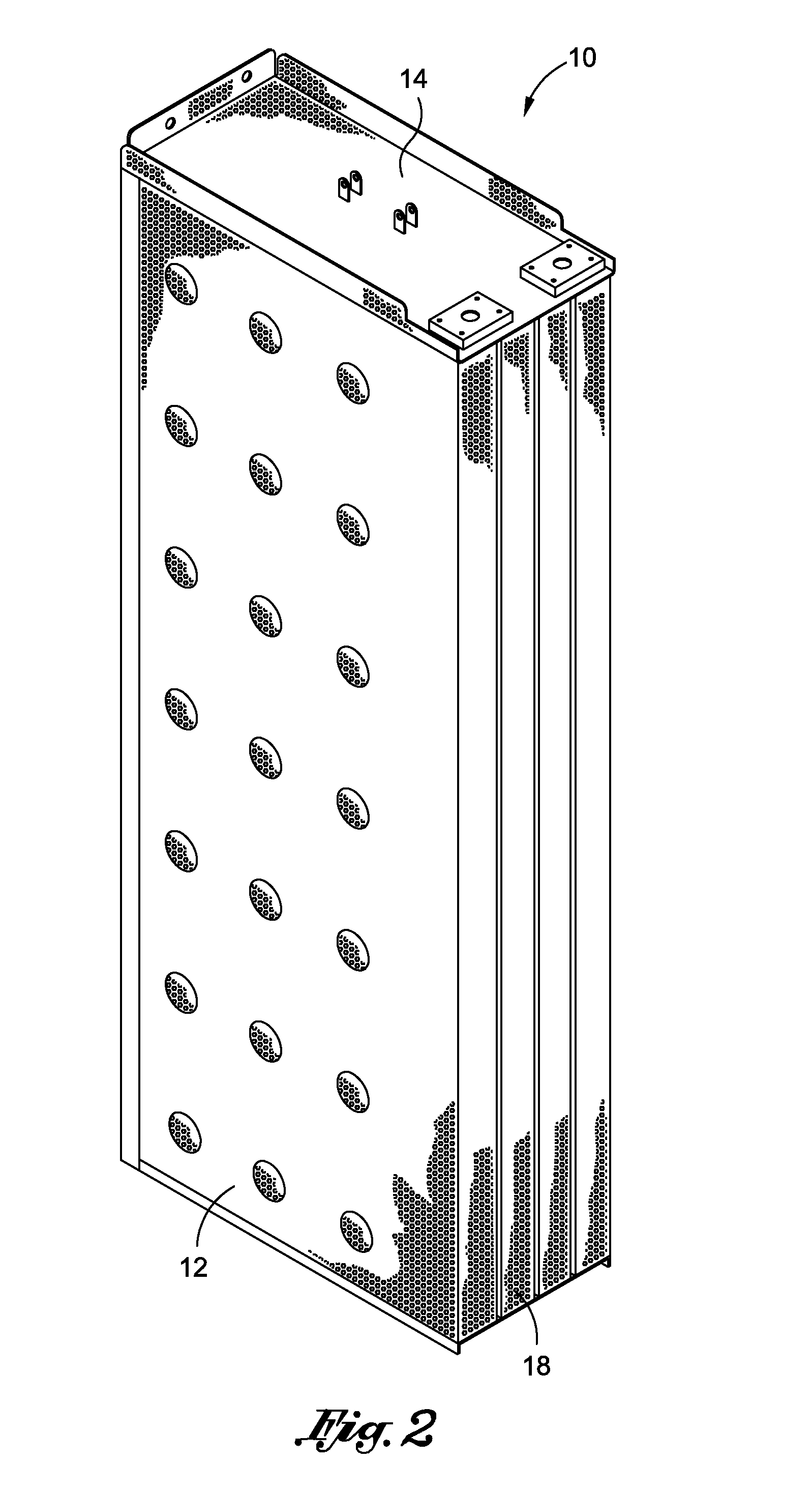
Enhanced nuclear sump strainer system

a strainer system and nuclear technology, applied in the direction of nuclear elements, separation processes, greenhouse gas reduction, etc., can solve the problems of affecting the cooling effect, affecting the flow rate of the emergency core cooling system, and losing the complex geometric surface advantages, etc., to facilitate the creation of a debris bed of low density, facilitate the creation of the bed, and reduce the effect of transportability

Active Publication Date: 2013-08-15
CONTROL COMPONENTS INC
View PDF8 Cites 14 Cited by
  • Summary
  • Abstract
  • Description
  • Claims
  • Application Information

AI Technical Summary

Benefits of technology

The present invention provides a debris interceptor that prevents debris from reaching the strainer module in a scenario of a post-loss of coolant accident. The debris interceptor traps the debris and prevents it from reaching the strainer surface. The interceptor has a membrane that opens when a predetermined pressure is reached, allowing a bypass flow path to the strainer surface and maintaining it clean. The interceptor can also have a layered stainless steel mesh to create a lower density debris bed that prevents the formation of a dense critical debris layer and increases the bed penetration, reducing head loss and debris bypass.

Problems solved by technology

A loss of coolant accident can involve the failure of reactor components that introduce large quantities of solid matter into the cooling water, which entrains the solids and carries them back to the suppression pool.
Thus, in both types of reactors (i.e., boiling water reactors and pressurized water reactors), cooling water is drawn from a reservoir and pumped to the reactor core, with entrained solids or debris potentially impairing cooling and damaging the emergency core cooling system pumps if permitted to circulate with the water.
The resulting fibrous debris bed on the strainer surfaces can quickly block the flow through the strainer, even though the trapped particulates may be small enough to pass through the strainer perforations.
Depending on the break location and its surrounding insulation configuration, the strainer may become so fully filled and coated with the fibrous insulation debris that it loses its complex geometric surface advantages, thus becoming a simple strainer.
This solution, however, is often undesirable since the available space in a reactor for a suction strainer is usually limited, and further because larger strainers are typically more costly.
As a result, the situation sometimes arises wherein the expected debris load after a loss of coolant accident can dictate a need for strainers that are too large for the available envelope for them in the containment area.
Moreover, large strainers are often more difficult work with and thus more costly to install.
In addition, prior art emergency core cooling system strainers have been constructed in ways that make them somewhat expensive to fabricate.

Method used


Image

  • Enhanced nuclear sump strainer system
  • Enhanced nuclear sump strainer system
  • Enhanced nuclear sump strainer system

Examples


first embodiment

[0033]Referring now to FIG. 5, the strainer module 28 of the strainer system 5 is shown as being outfitted with a debris interceptor 34 which comprises a sacrificial strainer screen 36 constructed in accordance with the present invention. The strainer screen 36 is cooperatively engaged to the strainer module 28 so as to protrude from the primary strainer surface defined thereby. As a result, an auxiliary suction plenum 37 is defined between the interior surface of the strainer screen 36 and the primary strainer surface of the strainer module 28.

[0034]In the exemplary embodiment shown in FIG. 5, the strainer screen 36 has a generally serpentine configuration. Due to its serpentine configuration, the strainer screen 36, when viewed from the perspective shown in FIG. 5, defines a spaced pair of top panels 38 which each have a generally triangular configuration. As will be recognized, the serpentine configuration of the strainer screen 36 results in the same defining a greater outer sur...

second embodiment

[0038]Referring now to FIG. 6, the strainer module 28 of the strainer system 5 is shown as being outfitted with a debris interceptor 34 which comprises a sacrificial secondary strainer 42 constructed in accordance with the present invention. The secondary strainer 42 is cooperatively engaged to the strainer module 28 so as to protrude from the primary strainer surface defined thereby. As a result, portions of the secondary strainer 42 and the primary strainer surface of the strainer module 28 collectively define an auxiliary suction plenum 43.

[0039]In the exemplary embodiment shown in FIG. 6, the secondary strainer 42 has a configuration which closely mirrors that of the underlying strainer module 28. In this regard, the secondary strainer 42 has a generally quadrangular configuration and is formed from a plurality of generally planar plates which are attached to each other in a prescribed arrangement. More particularly, when viewed from the perspective shown in FIG. 6, the secondar...

third embodiment

[0045]Referring now to FIG. 7, the strainer module 28 of the strainer system 5 is shown as being outfitted with a debris interceptor 34 which comprises a sacrificial mesh layer 62 constructed in accordance with the present invention. The mesh layer 62 is cooperatively engaged to the strainer module 28 so as to cover and protrude from the primary strainer surface defined thereby.

[0046]In the exemplary embodiment shown in FIG. 7, the mesh layer 62 is of a prescribed thickness, and is preferably fabricated from a layered stainless steel mesh such as Tissmetal® Type 450-16. The mesh layer 62 may be positioned over a perforated stainless steel plate which is sized and configured to cover the entirety of the primary strainer surface of the strainer module 28. The mesh layer 62 may alternatively comprise a stainless steel mesh screen with 62 are such that the entirety of the primary strainer surface of the strainer module 28, and thus then inflow ends 24 of each of the strainer pockets 22 ...


PUM

PropertyMeasurementUnit
Pressureaaaaaaaaaa
Flow rateaaaaaaaaaa
Sizeaaaaaaaaaa

Abstract

In accordance with the present invention, there is provided a strainer system for use in a nuclear sump. The strainer system of the present invention includes at least one primary strainer module which defines a primary strainer / filter surface. In the strainer system, the primary strainer surface of the primary strainer module has a debris interceptor which is cooperatively engaged thereto, and may be outfitted with one or more pressure released or activated membranes. In a loss of coolant accident, the debris interceptor, alone or in combination with the pressure activated membrane(s), is adapted to reduce the differential pressure experienced across the strainer system in nuclear power plants with medium to high fiber loads.

Description

CROSS-REFERENCE TO RELATED APPLICATIONS[0001]Not ApplicableSTATEMENT RE: FEDERALLY SPONSORED RESEARCH / DEVELOPMENT[0002]Not ApplicableBACKGROUND OF THE INVENTION[0003]1. Technical Field of the Invention[0004]The present invention relates generally to strainer devices and, more particularly, to a strainer system for use in a nuclear sump. The strainer system of the present invention includes at least one primary strainer module which defines a primary strainer / filter surface. The primary strainer surface of the primary strainer module includes a debris interceptor which is cooperatively engaged thereto, and comprises a screen or mesh layer which may be outfitted with one or more pressure released or activated membranes.[0005]2. Description of the Related Art[0006]A nuclear power plant typically includes an emergency core cooling system that circulates large quantities of cooling water to critical reactor areas in the event of accidents. A boiling water reactor or BWR commonly draws wa...

Claims


Application Information

Patent Timeline
IPC IPC(8): G21C19/00
CPCG21C15/18G21C19/307B01D29/58B01D29/27B01D29/52B01D35/30Y02E30/30
Inventor PRATHER, CARLGROB, DENISLEMCKE, CLAES
Owner CONTROL COMPONENTS INC
Learn More