
Phased antenna array including a plurality of electro-optical circuits having an optical source with an opto-electronic oscillator and associated methods

a phased antenna array and optical source technology, applied in the direction of antennas, electrical equipment, electromagnetic transmission, etc., can solve the problems of limited beam size, high manufacturing cost, and complex phased array antennas, and achieve the effect of effective operation

Inactive Publication Date: 2013-08-08
HARRIS CORP
View PDF4 Cites 14 Cited by
  • Summary
  • Abstract
  • Description
  • Claims
  • Application Information

AI Technical Summary

Benefits of technology

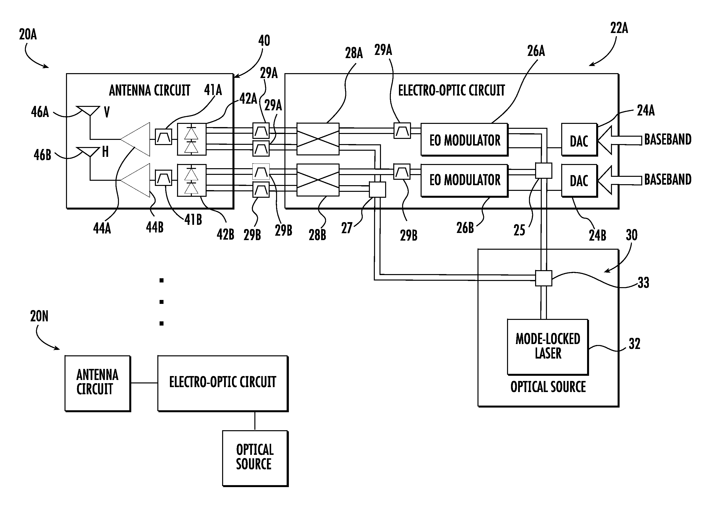
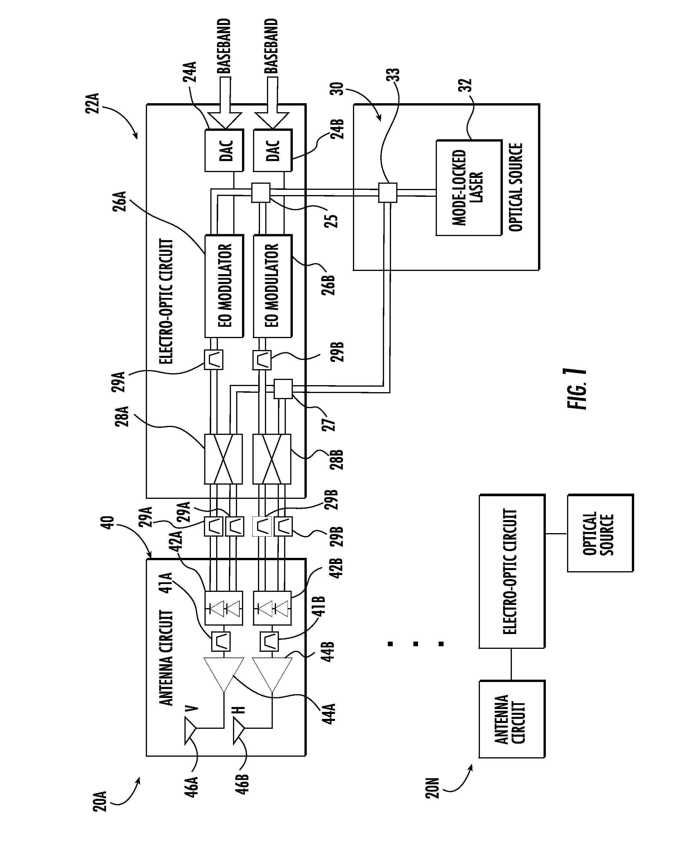
The present invention provides a phased antenna array that can effectively operate at high frequencies. It uses multiple antenna circuits that are spaced apart from EO circuits, each containing at least one photodiode and an antenna element. Optical fibers couple the EO circuits to the antenna circuits, which allows for more efficient processing of the electrical signal. This setup also allows for better performance at high frequencies.

Problems solved by technology

For example, millimeter wave, i.e. extremely high frequency (EHF), phased array antennas may be complex and costly to manufacture.
Furthermore, these phased array antennas may be limited in bandwidth and the number of beams.

Method used


Image

  • Phased antenna array including a plurality of electro-optical circuits having an optical source with an opto-electronic oscillator and associated methods
  • Phased antenna array including a plurality of electro-optical circuits having an optical source with an opto-electronic oscillator and associated methods
  • Phased antenna array including a plurality of electro-optical circuits having an optical source with an opto-electronic oscillator and associated methods

Examples


Embodiment Construction

[0020]The present invention will now be described more fully hereinafter with reference to the accompanying drawings, in which preferred embodiments of the invention are shown. This invention may, however, be embodied in many different forms and should not be construed as limited to the embodiments set forth herein. Rather, these embodiments are provided so that this disclosure will be thorough and complete, and will fully convey the scope of the invention to those skilled in the art. Like numbers refer to like elements throughout, and prime and multiple prime notation is used to indicate similar elements in alternative embodiments.

[0021]Referring initially to FIG. 1, a phased antenna array 20a . . . 20n is now described. For clarity, only the phased antenna 20a will be described, but it should be understood that there may be any number of such phased antennas. The phased antenna 20a includes a plurality of electro-optic (EO) circuits 22. Each EO circuit comprises a digital-to-analo...


PUM

PropertyMeasurementUnit
optical delayaaaaaaaaaa
electrical delayaaaaaaaaaa
opticalaaaaaaaaaa

Abstract

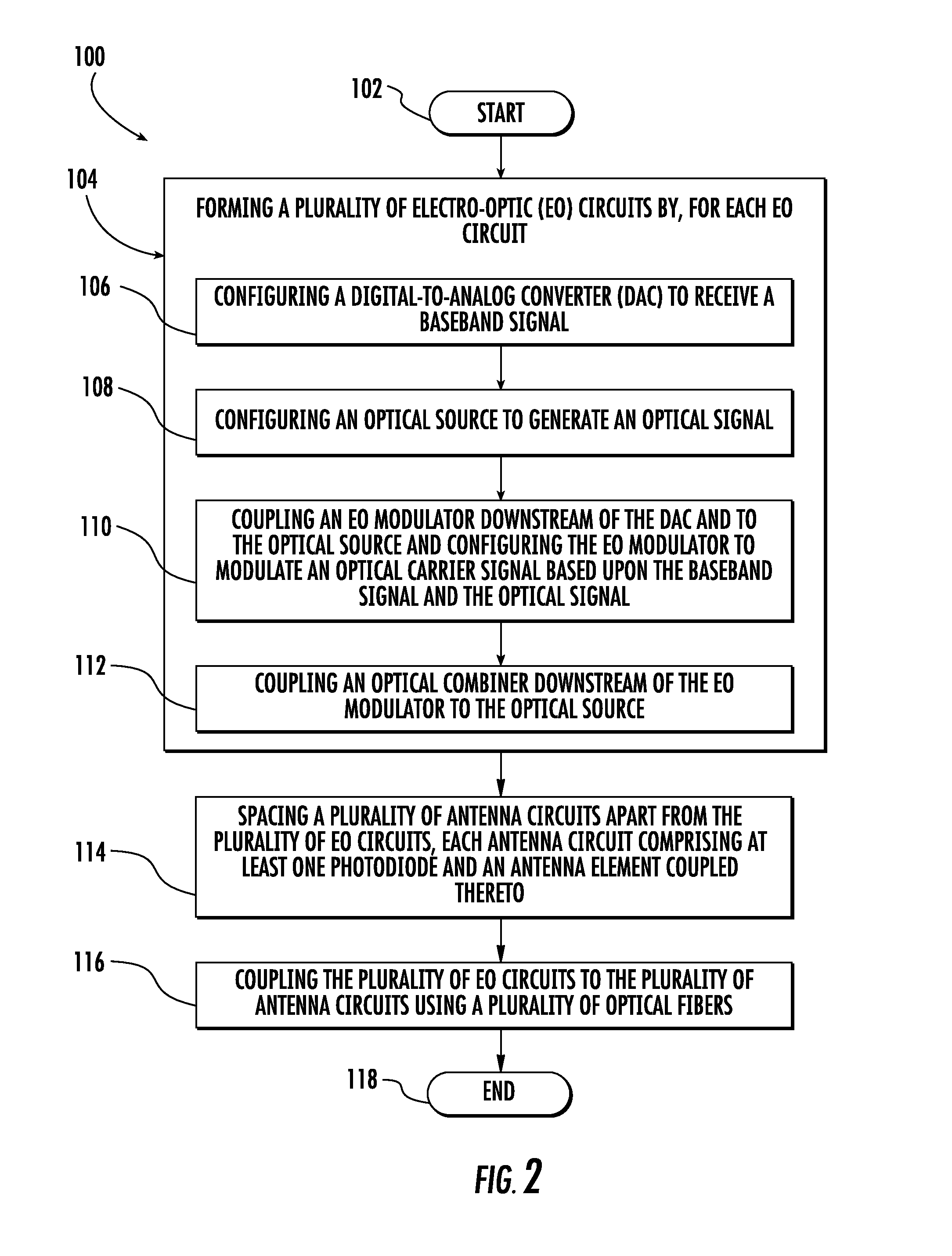
A phased antenna array includes a plurality of electro-optic (EO) circuits. Each EO circuit has a digital-to-analog converter (DAC) configured to receive a baseband signal, and an optical source comprising an opto-electronic oscillator configured to generate an optical signal. Each EO circuit also has an EO modulator coupled downstream of the DAC and to the optical source and configured to modulate an optical carrier signal based upon the baseband signal and the optical signal, and an optical combiner coupled downstream of the EO modulator and coupled to the optical source. In addition, there are a plurality of antenna circuits spaced apart from the plurality of EO circuits, each antenna circuit comprising at least one photodiode and an antenna element coupled thereto. Moreover, a plurality of optical fibers couple the plurality of EO circuits to the plurality of antenna circuits.

Description

FIELD OF THE INVENTION[0001]The present invention relates to the field of phased antenna arrays, and, more particularly, to phased antenna arrays with optical components and related methods.BACKGROUND OF THE INVENTION[0002]A typical wireless communications device includes an antenna, and a transceiver coupled to the antenna. The transceiver and the antenna cooperate to transmit and receive communications signals.[0003]One particularly advantageous antenna type is the phased array antenna. The phased array antenna comprises a plurality of antenna elements, and processing circuitry to vary the related phase of the signals received from the individual antenna elements or sent to the antenna elements. The varying of the related phase of the antenna elements may provide for changing the effective radiation pattern of the antenna. In particular, the radiation pattern can be changed to be highly directional, i.e. reinforcing signals received from one direction and rejecting those received ...

Claims


Application Information

Patent Timeline
Patent Type & Authority Applications(United States)
IPC IPC(8): H04B10/10H01P11/00
CPCY10T29/49018H01Q3/2676
Inventor MIDDLETON, CHARLESMAST, ALANKRALOVEC, JAYDESALVO, RICHARDDEIBNER, GUS W.PHILO, JEFF
Owner HARRIS CORP
Learn More