
Method for Calibrating a Drive Motor for a Toner Metering Device in an Imaging Apparatus

Active Publication Date: 2013-08-08
LEXMARK INT INC
View PDF12 Cites 35 Cited by
  • Summary
  • Abstract
  • Description
  • Claims
  • Application Information

AI Technical Summary

Benefits of technology

The patent describes a method for adjusting the back EMF constant in an imaging apparatus to control the speed of a DC motor that drives a toner metering device. The method involves measuring the time it takes for the motor to rotate the toner metering device and making multiple back EMF measurements, which are then averaged and used to estimate the motor's speed. The actual speed is then calculated based on the motor's gear ratio and the time it takes to rotate. The back EMF constant is then adjusted based on the estimated and actual speeds, and the adjusted value is stored for use in the next calibration cycle. This method makes it easier to control the speed of the motor and ensures consistent performance of the toner metering device.

Problems solved by technology

These sensors provide highly accurate information about the motor speed, however, they add about cost in material and in assembly.
However a single channel encoder cannot tell the direction of the motor rotation so an additional sensor is needed to determine rotational direction of the toner metering device.
Also with a single channel encoder any signals generated from vibrations or electrical noise will cause the accurate information of the toner metering mechanism to be lost.
However, the quadrature encoders are expensive.
One potential problem is that when the stepper motor is turned off, there is no guarantee that the stepper motor can start at the same position, leading to some uncertainty about the position of the toner metering device.
Stepper motors are also prone to acoustical noise and excessive power consumption due to their extremely inefficient operation.
However, one drawback of the technique is that the measured speed is only as accurate as the estimation of the back EMF constant Ke.
For some applications, this amount of error in motor speed is unacceptable.

Method used


Image

  • Method for Calibrating a Drive Motor for a Toner Metering Device in an Imaging Apparatus
  • Method for Calibrating a Drive Motor for a Toner Metering Device in an Imaging Apparatus
  • Method for Calibrating a Drive Motor for a Toner Metering Device in an Imaging Apparatus

Examples


Embodiment Construction

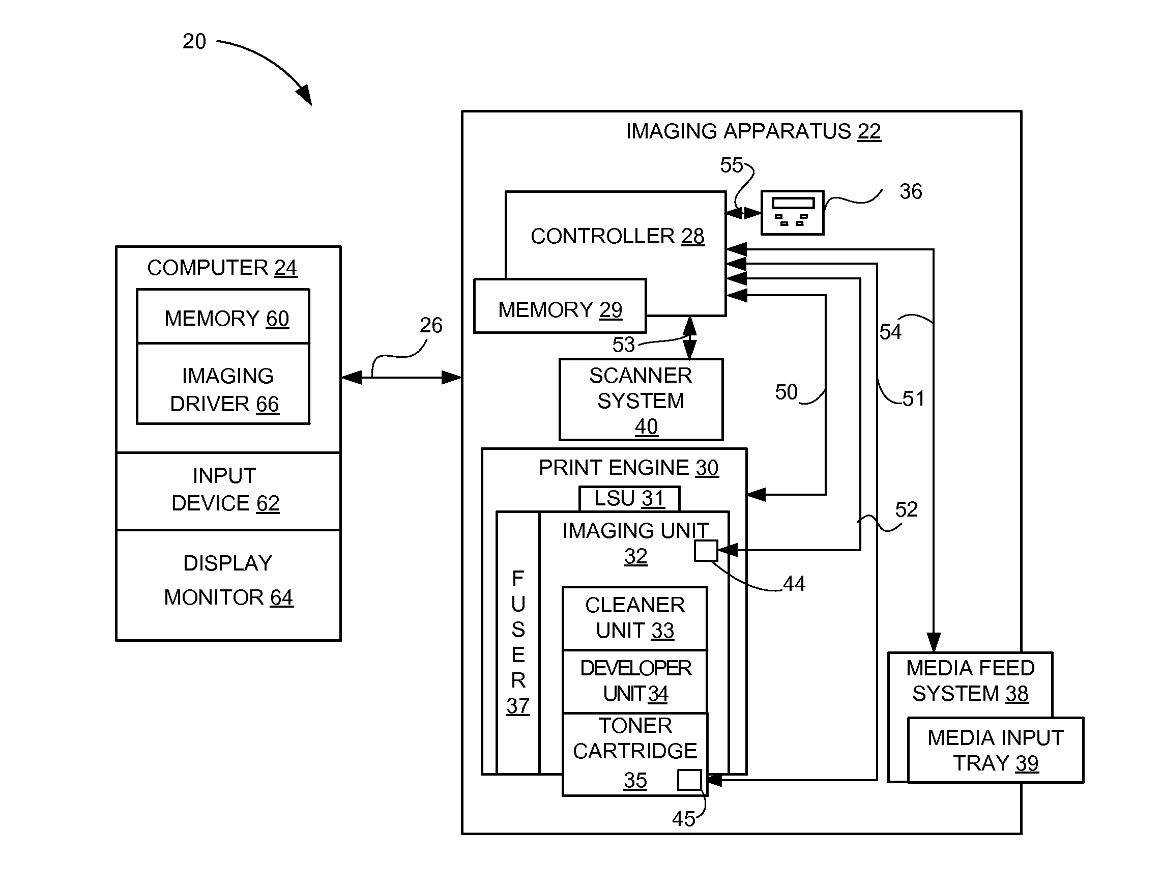
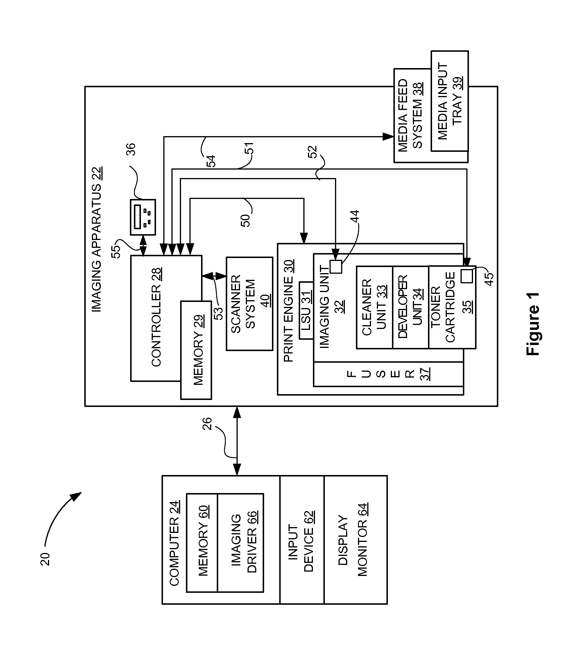
[0028]It is to be understood that the present disclosure is not limited in its application to the details of construction and the arrangement of components set forth in the following description or illustrated in the drawings. The present disclosure is capable of other embodiments and of being practiced or of being carried out in various ways. Also, it is to be understood that the phraseology and terminology used herein is for the purpose of description and should not be regarded as limiting. The use of “including,”“comprising,” or “having” and variations thereof herein is meant to encompass the items listed thereafter and equivalents thereof as well as additional items. Unless limited otherwise, the terms “connected,”“coupled,” and “mounted,” and variations thereof herein are used broadly and encompass direct and indirect connections, couplings, and mountings. In addition, the terms “connected” and “coupled” and variations thereof are not restricted to physical or mechanical connec...


PUM


Abstract

In an imaging apparatus having a toner container, a method of periodically calibrating a back EMF constant Ke used in a speed control circuit of a DC motor used for driving for a toner metering device. To adjust the value of the back EMF constant Ke, the method uses a plurality of sampled back EMF measurements together with a calculated actual speed of rotation of the toner metering device as measured using motion sensor.

Description

CROSS REFERENCES TO RELATED APPLICATIONS[0001]None.STATEMENT REGARDING FEDERALLY SPONSORED RESEARCH OR DEVELOPMENT[0002]None.REFERENCE TO SEQUENTIAL LISTING, ETC.[0003]None.BACKGROUND[0004]1. Field of the Disclosure[0005]The present disclosure relates generally to motor speed controls, and more particularly to those used for toner metering devices.[0006]2. Description of the Related Art[0007]In electrophotographic imaging apparatus, motor driven toner metering devices are used to convey toner from a toner reservoir for use in the imaging unit of the imaging apparatus. DC motors are typically used to drive toner feed mechanisms. A brush DC motor can provide enough torque and speed range to drive the toner metering system. Accurate rotational speed control of these motors ensures reliable operation of the imaging apparatus. To achieve good speed control, a way to measure the motor speed accurately is needed. There are several methods to measure a speed of a brush DC motor. One could m...

Claims


Application Information

Patent Timeline
IPC IPC(8): H02P7/285
CPCH02P7/29G03G15/0877G03G15/0856H02P23/14
Inventor BROWN, TIMOTHY LEOKENJI, TOTSUKA
Owner LEXMARK INT INC
Learn More