
Techniques for Grid Coupling Photovoltaic Cells Using Ratiometric Voltage Conversion

a technology of ratiometric voltage conversion and photovoltaic cells, applied in the direction of dc network circuit arrangement, dc source parallel operation, semiconductor devices, etc., can solve the problems of series connected cells, limited performance, and thus limited power point to less than optimal performance, and increase the severity of limitation

Inactive Publication Date: 2013-08-08
KING ABDULAZIZ CITY FOR SCIENCE AND TECHNOLOGY +1
View PDF24 Cites 18 Cited by
  • Summary
  • Abstract
  • Description
  • Claims
  • Application Information

AI Technical Summary

Benefits of technology

The present invention provides techniques for transferring electrical power in photovoltaic systems. It introduces a DC to DC converter that can alter the voltage output from the photovoltaic power producing elements and receive power from the grid in a more efficient manner. The invention can be applied to different types of photovoltaic cells, such as concentrator photovoltaic cells, and can be used in both commercial and residential settings. The technical effects of the invention are improved performance and reliability of photovoltaic systems, enhanced efficiency of power conversion, and reduced cost of power distribution.

Problems solved by technology

Series connected cells are, however, performance limited by the weakest cell(s) in the string.
Cells that are operating at a current other than the maximum power point will thus be limited to less than optimal performance.
This limitation increases in severity with concentration.
In the case of parallel connected cells, the current produced is large and the voltage too low to be useful for most applications.
Also, producing large current is costly in terms of resistive losses and the amount of conductor necessary to connect the system.
Also, regardless of the connection scheme, it is common that the cells are mismatched with regard to current and / or voltage relative to the device(s) to which the power is being supplied.

Method used


Image

  • Techniques for Grid Coupling Photovoltaic Cells Using Ratiometric Voltage Conversion
  • Techniques for Grid Coupling Photovoltaic Cells Using Ratiometric Voltage Conversion
  • Techniques for Grid Coupling Photovoltaic Cells Using Ratiometric Voltage Conversion

Examples


Embodiment Construction

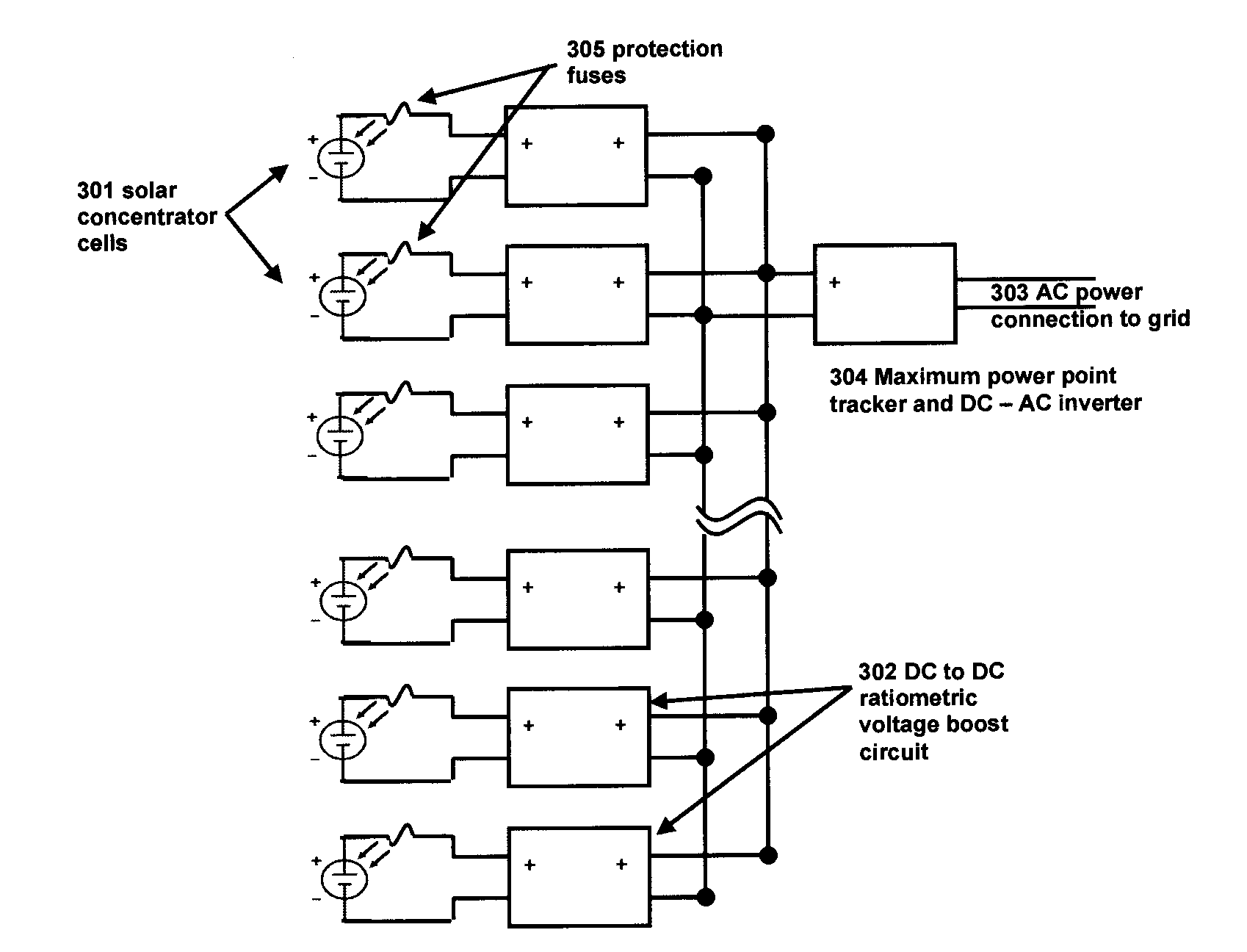
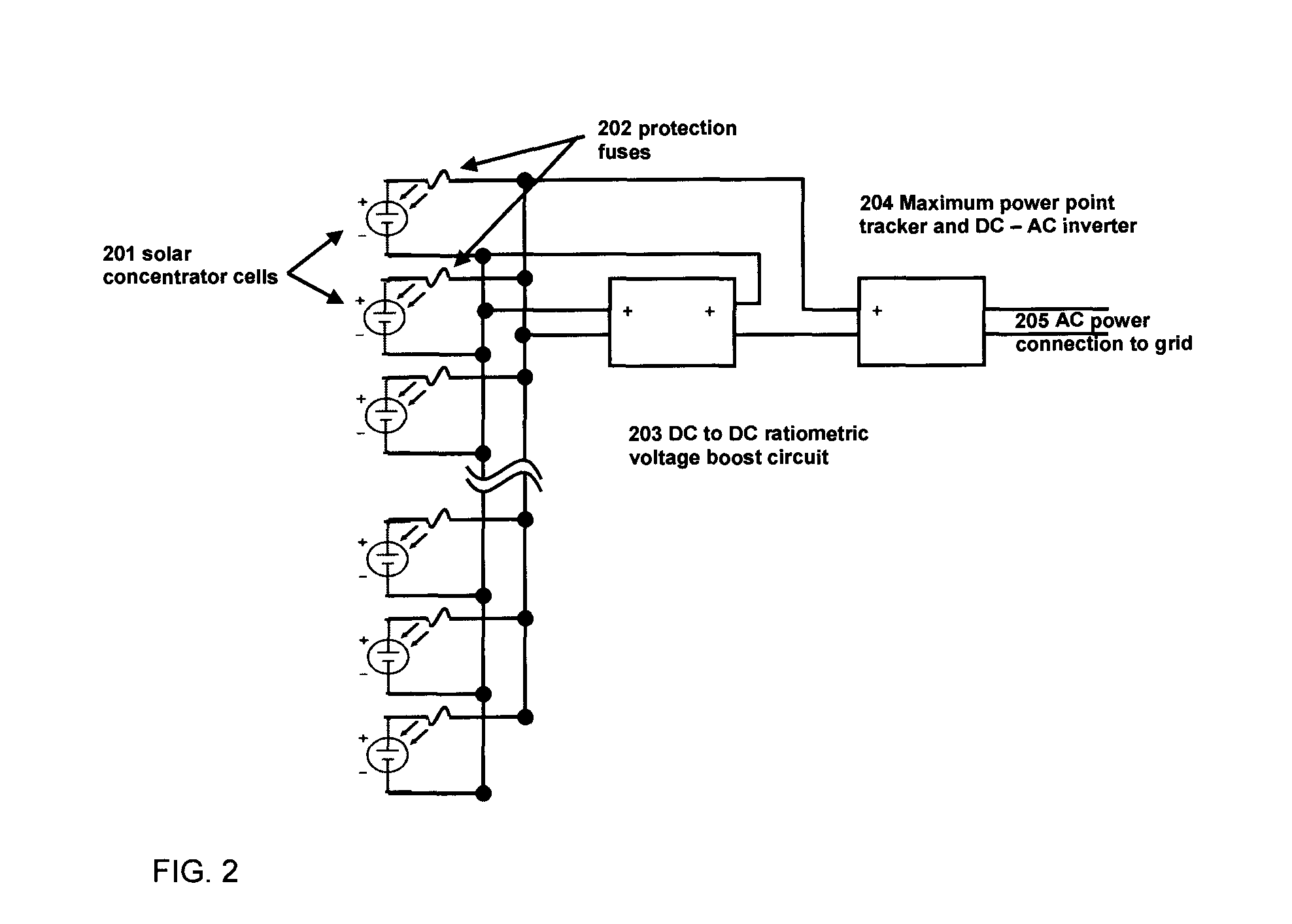
[0016]Provided herein are techniques for connection of photovoltaic power producing elements, such as photovoltaic cells, to power conditioning and grid tie circuitry. With concentrator photovoltaic cells in particular, these systems are characterized by significantly higher cell currents and increasingly larger distances between cells. In some applications individual cell currents can reach 30 amps per square centimeter of cell area. At these current levels, connectors become expensive and very thick wires are required to connect cells. Thus, maximizing performance from a grid connected array of photovoltaic power producing elements is important, especially in the case of concentrator photovoltaic systems.

[0017]The circuits described herein utilize a ratiometric DC to DC converter. In general, a DC to DC converter is a type of power converter circuit that can convert a source of direct current (DC) from one voltage level to another. In particular, a ratiometric DC to DC converter i...


PUM


Abstract

Techniques for electrical power transfer in photovoltaic systems are provided. In one aspect, a photovoltaic system includes an array of photovoltaic power producing elements (e.g., concentrator photovoltaic cells); a power receiving unit; and at least one ratiometric DC to DC converter connected to both the array of photovoltaic power producing elements and the power receiving unit. The array of photovoltaic power producing elements can include a plurality of the photovoltaic power producing elements connected in series or in parallel. In another aspect, a method of transferring electrical power from an array of photovoltaic power producing elements to a power receiving unit includes the following step. At least one ratiometric DC to DC converter is connected to both the array of photovoltaic power producing elements and the power receiving unit. The at least one ratiometric DC to DC converter is configured to alter a voltage output from the array.

Description

FIELD OF THE INVENTION[0001]The present invention relates to photovoltaic power systems and more particularly, to concentrator photovoltaic power systems.BACKGROUND OF THE INVENTION[0002]Solar photovoltaic power systems electrically connect multiple photovoltaic cells to the power grid. In a typical system this is achieved by serially connecting individual cells to produce high DC voltage and low current. Arrays of these serially connected cells are subsequently connected in serial and parallel topographies to produce strings operating at approximately 600 V peak.[0003]Series connected cells are, however, performance limited by the weakest cell(s) in the string. In a series connected circuit, the current through all cells is the same. Cells that are operating at a current other than the maximum power point will thus be limited to less than optimal performance. This limitation increases in severity with concentration. In the case of parallel connected cells, the current produced is l...

Claims


Application Information

Patent Timeline
IPC IPC(8): H02J1/00
CPCY02E10/58H02J1/12H02J3/385H01L31/02021H02J2300/26H02J3/381Y02E10/56H02J3/46H02J3/383
Inventor KIRCHNER, PETER DANIELMANZER, DENNIS G.MARTIN, YVES C.PICUNKO, THOMASSANDSTROM, ROBERT L.VAN KESSEL, THEODORE GERARD
Owner KING ABDULAZIZ CITY FOR SCIENCE AND TECHNOLOGY
Learn More