
Imaging apparatus and method for controlling the same

a touch panel and apparatus technology, applied in the field of imaging apparatus, can solve the problem that the method of setting an auto-bracketing value with good operability using a touch panel has not been sufficiently considered, and achieve the effect of good operability

Active Publication Date: 2013-07-11
CANON KK
View PDF11 Cites 43 Cited by
  • Summary
  • Abstract
  • Description
  • Claims
  • Application Information

AI Technical Summary

Benefits of technology

The present invention is about an imaging machine that allows users to easily set the autobracketing value using a touch panel. The technical effect of this innovation is that it provides users with simple and efficient means to set the autobracketing value, making the imaging process more user-friendly and convenient.

Problems solved by technology

In the techniques discussed in the patent documents, however, a method for setting an autobracketing value with good operability using a touch panel has not been sufficiently considered.

Method used


Image

  • Imaging apparatus and method for controlling the same
  • Imaging apparatus and method for controlling the same
  • Imaging apparatus and method for controlling the same

Examples


Embodiment Construction

[0022]Various exemplary embodiments, features, and aspects of the invention will be described in detail below with reference to the drawings. It is to be noted that the following exemplary embodiment is merely one example for implementing the present invention and can be appropriately modified or changed depending on individual constructions and various conditions of apparatuses to which the present invention is applied. Thus, the present invention is in no way limited to the following exemplary embodiment.

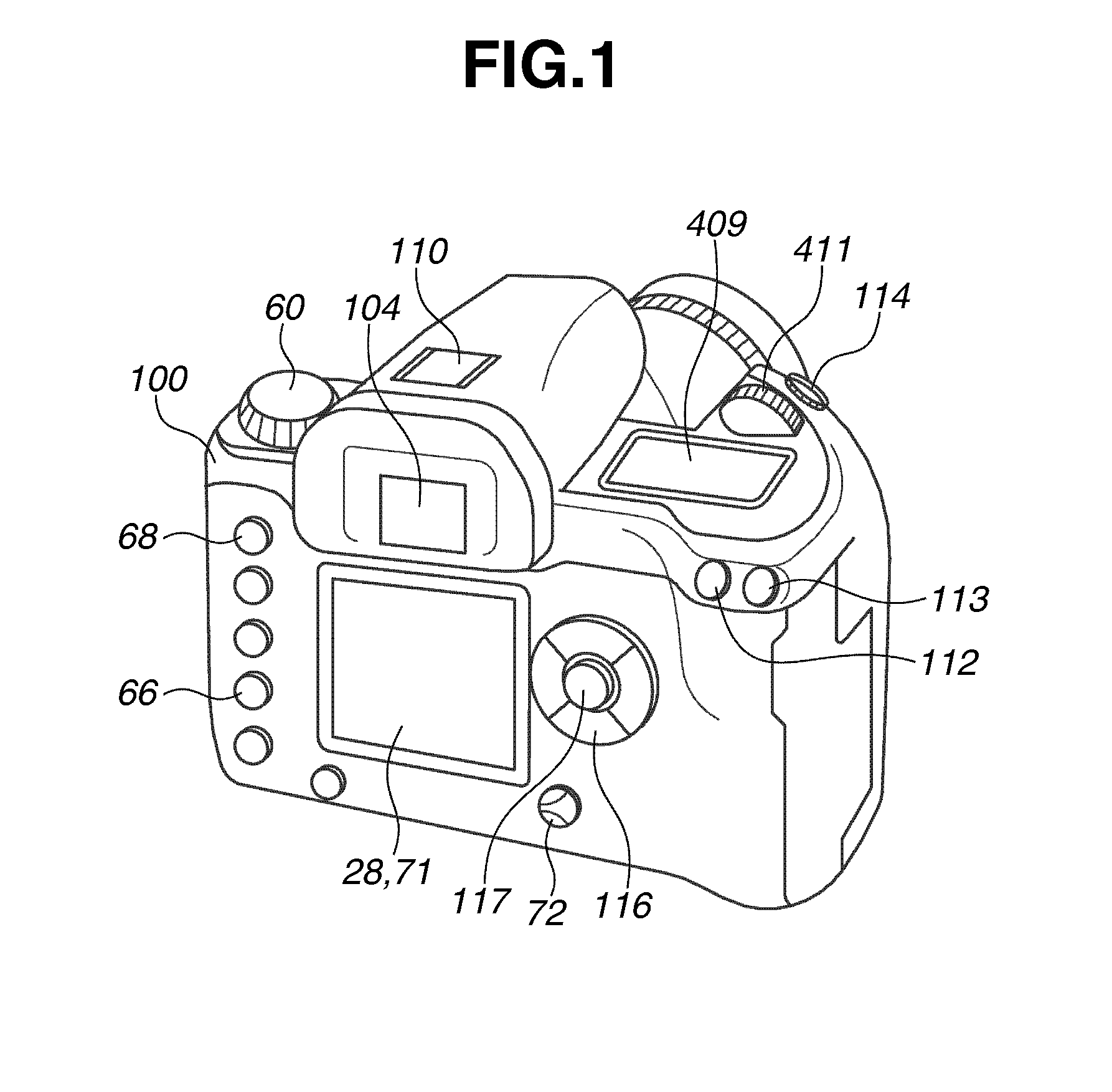
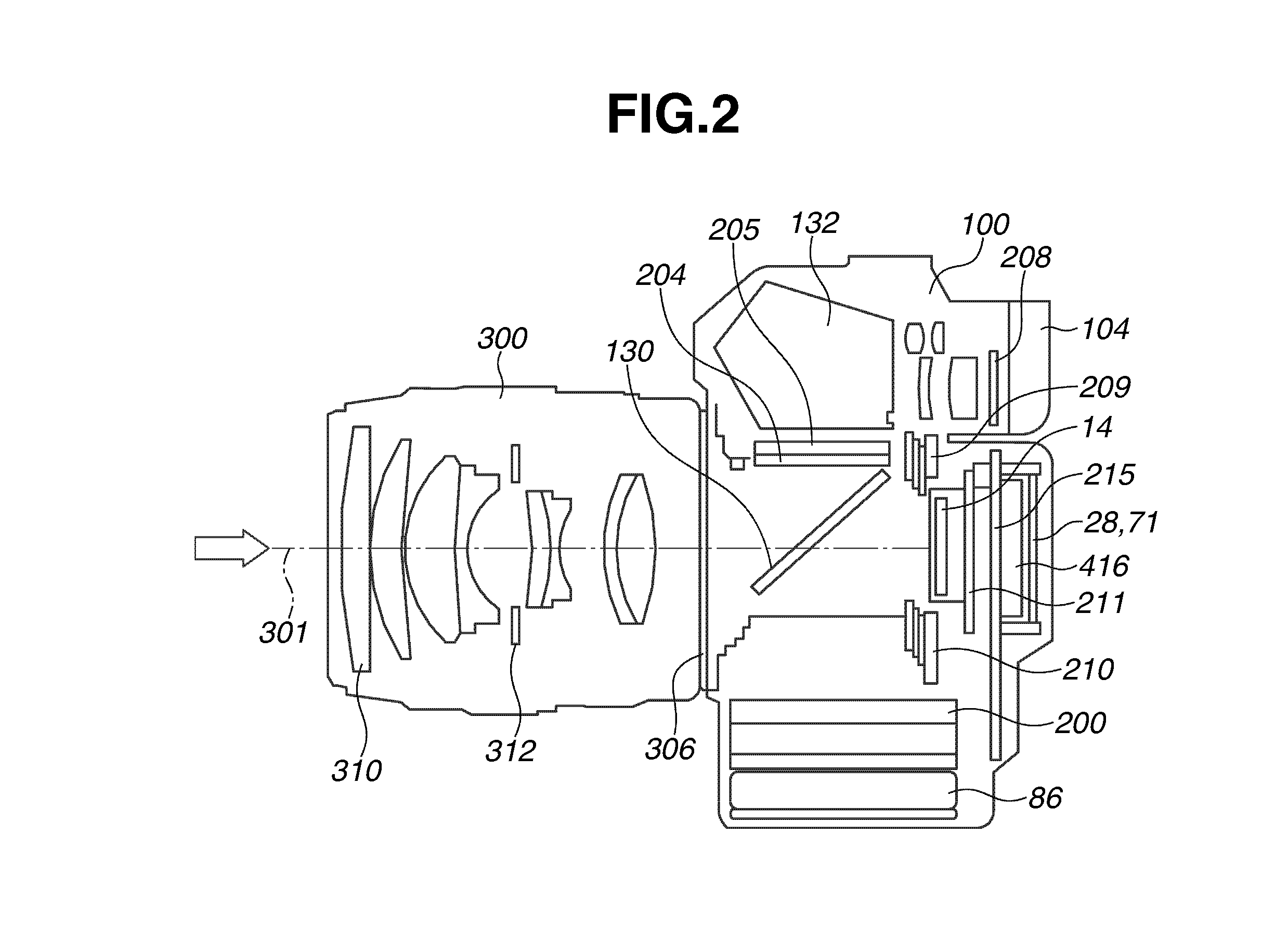
[0023]FIG. 1 illustrates the appearance of an imaging apparatus according to an exemplary embodiment of the present invention. FIG. 2 is a schematic diagram illustrating an internal configuration of the imaging apparatus illustrated in FIG. 1. The imaging apparatus illustrated in FIGS. 1 and 2 is configured as a digital single-lens reflex camera 100 (hereinafter referred to as a camera body).

[0024]On the upper surface of the camera body 100 are provided an accessory shoe 110, an o...


PUM


Abstract

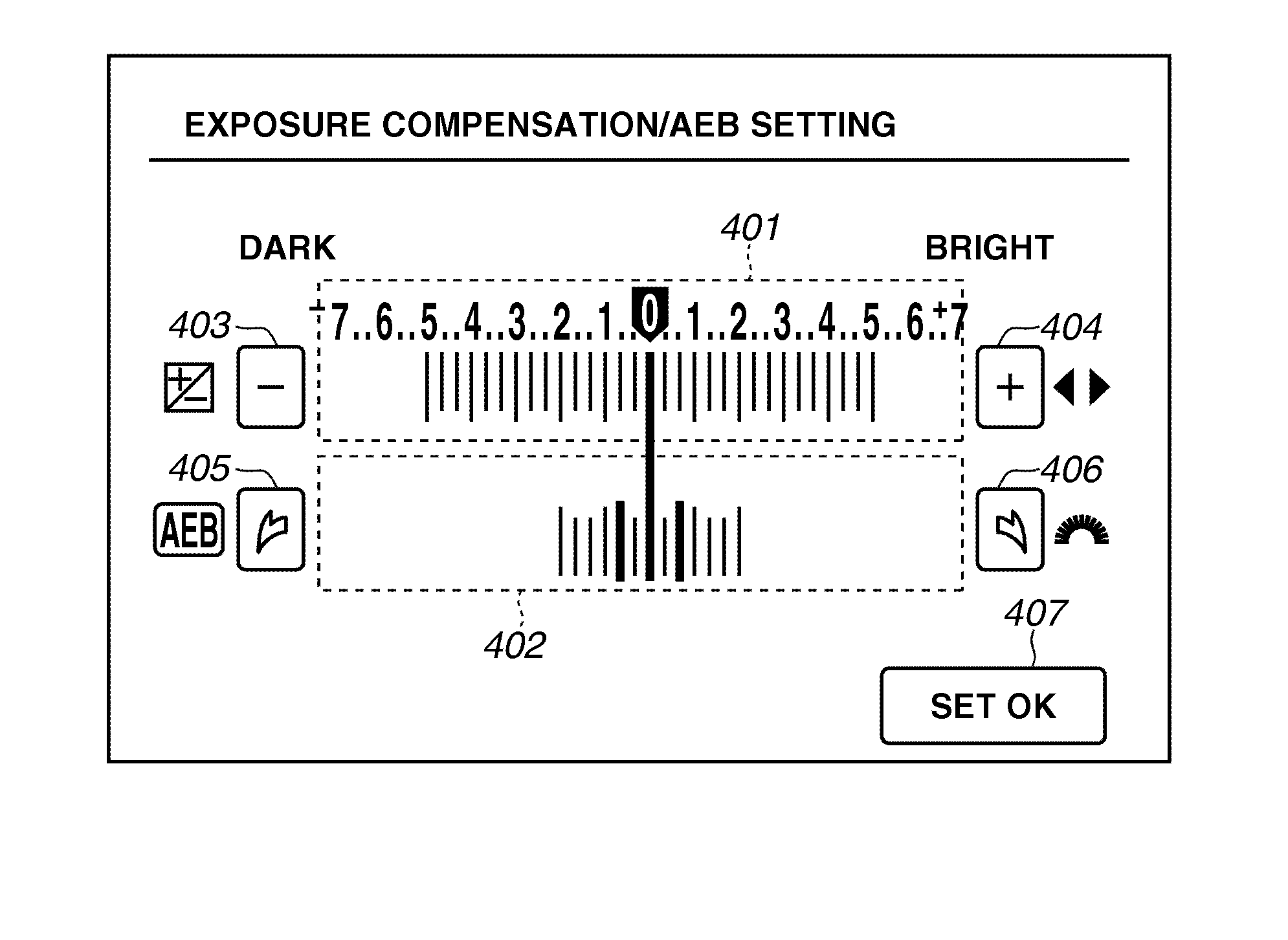
An imaging apparatus includes a touch detection unit configured to detect a touch operation on a display unit, a display control unit configured to control display of an indicator indicating a reference value in an autobracketing shooting and an indicator indicating a bracketing value in the autobracketing shooting, a control unit configured to perform control to increase a width between the reference value and the bracketing value to be set when the touch detection unit detects a touch operation moving in a first direction while keeping touching a setting area for setting the bracketing value on the display unit and to decrease the width when the touch detection unit detects a touch operation moving in a second direction opposite the first direction while keeping touching the setting area, and a bracketing value setting unit configured to set the bracketing value based on the width.

Description

BACKGROUND OF THE INVENTION[0001]1. Field of the Invention[0002]The present invention relates to an imaging apparatus and a method for controlling the same. The present invention relates in particular to an imaging apparatus which sets a parameter of autobracketing using a touch panel, and a method for controlling the same.[0003]2. Description of the Related Art[0004]Until now, there has been an imaging apparatus such as a digital camera which is equipped with an autobracketing function to acquire a plurality of captured images with slightly different settings in which a specific setting value is automatically shifted from a reference value. There has also been an imaging apparatus having an exposure compensation function in which a user compensates a correct exposure value automatically set by the imaging apparatus. Furthermore, an imaging apparatus combining the exposure compensation and autobracketing functions has been proposed. Japanese Patent Application Laid-Open No. 2010-454...

Claims


Application Information

Patent Timeline
Patent Type & Authority Applications(United States)
IPC IPC(8): G06F3/0484
CPCG03B17/20G06F3/04845H04N5/2356G06F3/04847H04N5/23293G06F3/0488H04N23/633H04N23/631H04N23/743
Inventor IZAKI, YUKO
Owner CANON KK
Learn More