
Method for monitoring a transmitter and corresponding transmitter

a transmitter and transmitter technology, applied in the field of method for monitoring a transmitter, can solve the problems of complex and/or cost-intensive, both redundant and also diverse configurations, and the need for a second unit for processing raw signals, etc., and achieve the effect of increasing the safe failure fraction

Active Publication Date: 2013-07-11
KROHNE MESSTECHNICK GMBH & CO KG
View PDF11 Cites 3 Cited by
  • Summary
  • Abstract
  • Description
  • Claims
  • Application Information

AI Technical Summary

Benefits of technology

The present invention provides a method for monitoring a transmitter to increase its safety failure fraction. The method involves measuring a signal and comparing it to a stored signal to detect any errors. If there is no error, the signal is transmitted. If there is an error, the method triggers a protective state or alerts the transmission unit for further communication. The invention advantageously allows for testing the presence of an error without the need for a separate unit, making it more compact and economical. Additionally, the method allows for glancing out of the transmitter to verify the signal transmission element is carrying the correct signal.

Problems solved by technology

Both redundant and also diverse configurations are generally complex and / or cost-intensive.
It is disadvantageous that a second unit must be provided for processing of the raw signal.
A safe error is an error which is relevant to safety and which however either is recognized or transfers the transmitter into a safe state.

Method used


Image

  • Method for monitoring a transmitter and corresponding transmitter
  • Method for monitoring a transmitter and corresponding transmitter
  • Method for monitoring a transmitter and corresponding transmitter

Examples


Embodiment Construction

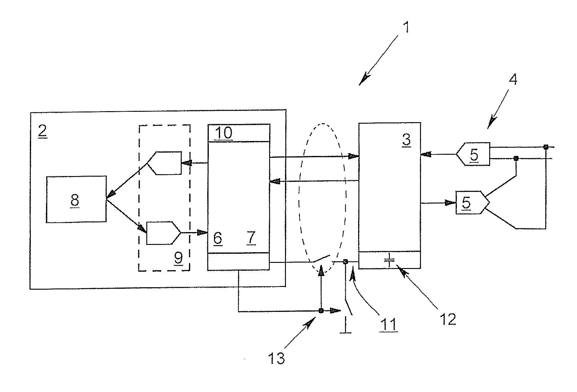
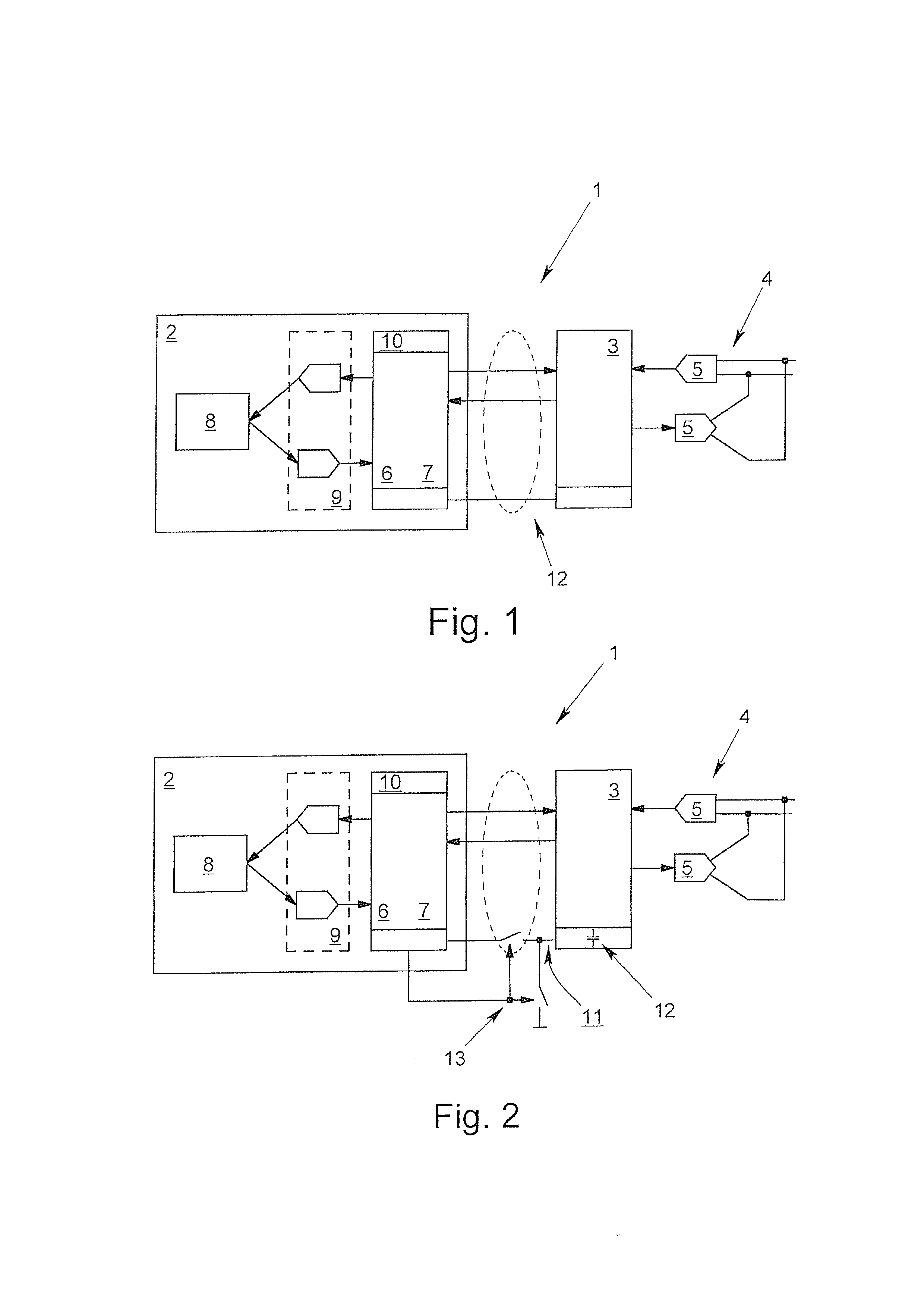
[0031]FIGS. 1 & 2 each show different exemplary embodiments of a transmitter 1, the figures not being representations in the sense of correct electrical wiring diagrams, but rather indicating the active relationships between the different components of the transmitter 1. The signal characteristic which is shown in FIG. 3, fundamentally, shows the possible characteristics of voltage signals as can occur following the use of the method in accordance with the invention or in a transmitter in accordance with the invention. The characteristic of one exemplary embodiment in FIG. 4, fundamentally, describes a progression of steps, another grouping or another sequence likewise being possible and being within the scope of the invention.

[0032]The block diagram of FIG. 1 shows a transmitter 1 in accordance with the invention which has a measurement unit 2 and a transmission unit 3. Proceeding from a measurement of a physical and / or chemical measurement quantity or process quantity, the measure...


PUM


Abstract

A method for monitoring a transmitter (1) with a measurement (2) and a transmission unit (3), with which a measurement (2) signal is generated that is dependent on a measurement quantity, and with the transmission unit (3) receiving the measurement signal, and based on the measurement signal, an output signal is transferred to a signal transmission element (4). To makes it possible to recognize an error, an input signal is taken from the signal transmission element (4) and is transferred to the measurement unit (2) as a comparison signal which corresponds to the input is compared with a stored signal and based upon the outcome of the comparison, either the measurement signal is transferred from the measurement unit (2) to the transmission unit (3) or the transmission unit (3) is shifted into a definable state and an error signal is transferred to it.

Description

BACKGROUND OF THE INVENTION[0001]1. Field of the Invention[0002]The invention relates to a method for monitoring a transmitter. Here, the transmitter comprises at least one measurement unit and one transmission unit. The measurement unit and the transmission unit are interconnected at least for transmission of signals. The measurement unit is used to determine at least one measurement quantity and to produce a measurement signal which is dependent on it. The transmission unit receives the measurement signal from the measurement unit and is used to transfer an output signal to at least one signal transmission element, based on the measurement signal. The invention also relates to a corresponding transmitter which comprises at least one measurement unit and one transmission unit.[0003]2. Description of Related Art[0004]Transmitters—alternative names are transducers or field devices—of the aforementioned type have been known for a long time and are used quite generally to detect the pr...

Claims


Application Information

Patent Timeline
Patent Type & Authority Applications(United States)
IPC IPC(8): H04B17/00
CPCH04B17/17G01D18/00G05B23/0291G05B2219/14114G06F11/07
Inventor PICHOT, VINCENT
Owner KROHNE MESSTECHNICK GMBH & CO KG
Learn More