Lamp socket type camera

Inactive Publication Date: 2013-07-04
LIU DA MING
View PDF12 Cites 89 Cited by
  • Summary
  • Abstract
  • Description
  • Claims
  • Application Information

AI Technical Summary

Benefits of technology

The present invention relates to a lamp socket type camera that solves the problems of conventional cameras, such as difficult installation and additional wiring costs. The lamp socket type camera has a simpler installation process, uses a common lamp socket, and savors labor and cost. It features an image capturing element, a power module, a control module, a wireless transmission module, and a sliding housing. The sliding housing has a light-permeable aperture and the image capturing element captures image data from the outside through the aperture and transmits it wirelessly via the wireless transmission module. The camera installation process is simplified because it can be easily connected to a lamp socket and adjusted. Additionally, the image capturing element is pivotally provided in the sliding housing, allowing for various image capturing angles, and a cap and cover provide protection for the image capturing element.

Problems solved by technology

If no suitable power sources are available where a camera is to be installed, extra time and money must be spent for wiring and for the additional installation of related power equipment, which significantly increases the cost and difficulty of camera installation.
Moreover, the camera must be fixed to the ceiling or the wall by means of fasteners (e.g., screws) and tools, which adds to the time and labor required for camera installation.
Not only that, the camera, once installed, cannot be readily moved to other installation positions according to practical needs; as a result, the camera only provides limited use and is not convenient enough.

Method used


Image

  • Lamp socket type camera
  • Lamp socket type camera
  • Lamp socket type camera

Examples


Embodiment Construction

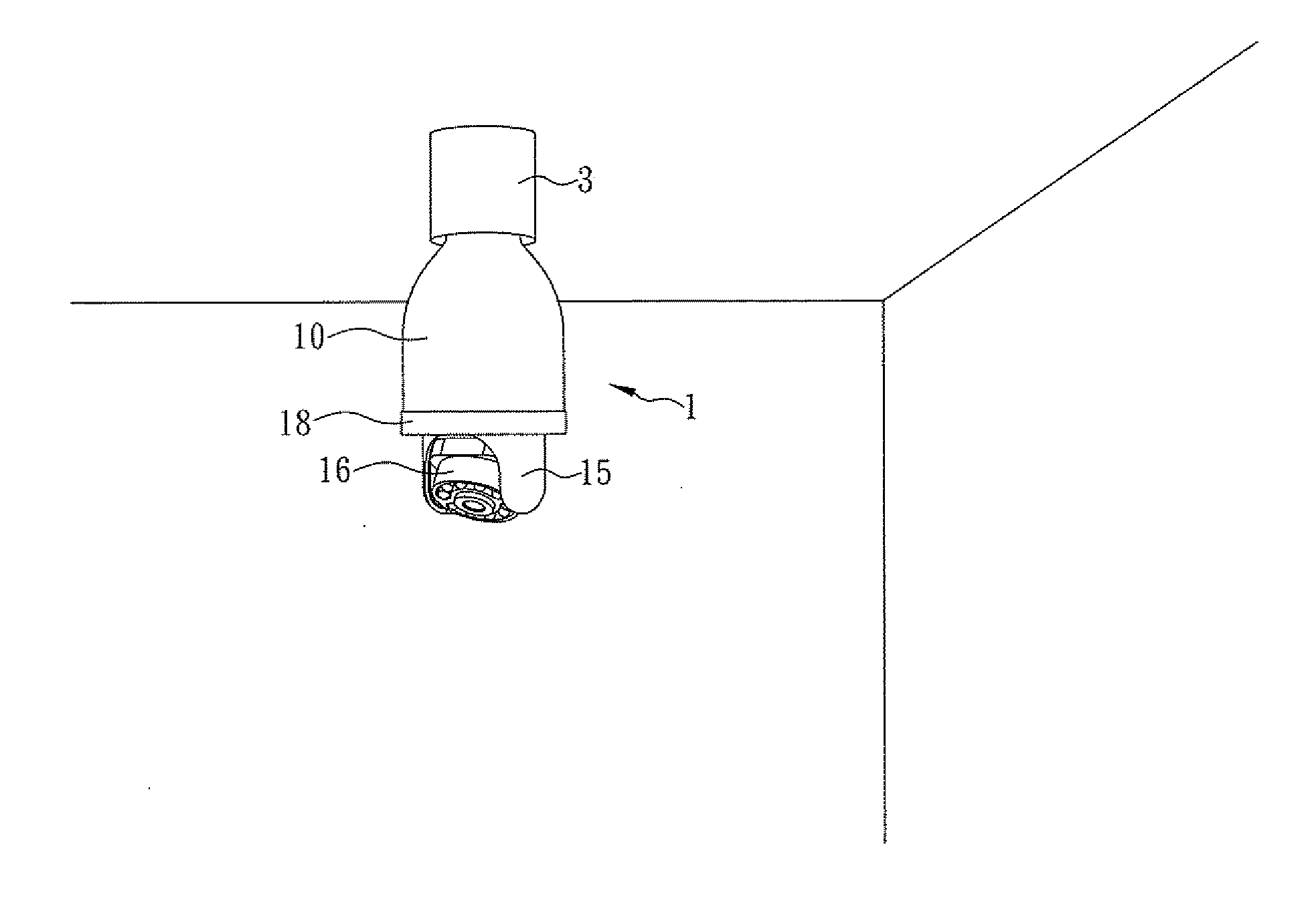
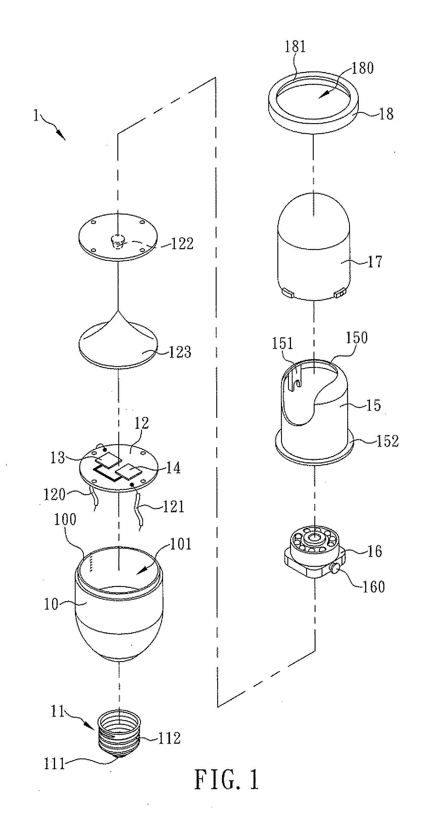
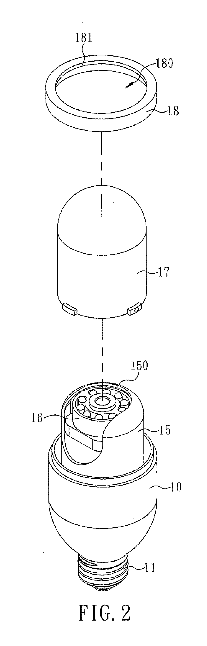
[0014]The inventor of the present invention has long been engaged in the research and development of cameras and related products. In the process, the inventor has found that installation of the conventional cameras is undesirably costly, complicated, and time-consuming not only because power cables and signal transmission lines must be in place before the cameras can be installed, but also because fasteners such as screws are required to fix the cameras to the ceiling or the wall. While attempts have been made to improve the conventional cameras, an ideal solution has yet to be found. In consideration of the above, the inventor came up with the idea of incorporating an existing bulb socket into a camera and thereby making a lamp socket type camera which can be directly installed in a common lamp socket. By substantially simplifying the camera installation process, the time and labor otherwise required can be saved.

[0015]The present invention discloses a lamp socket type camera. Ref...


PUM


Abstract

The present invention is to provide a lamp socket type camera which includes an outer housing, a bulb socket connected to the outer housing and capable of being threadedly and electrically connected to an existing lamp socket for receiving electric power from the lamp socket, a power module received in the receiving space and electrically connected to the bulb socket for converting the electric power received from the bulb socket into a required specification, a control module received in the receiving space and connected to the power module, a wireless transmission module received in the receiving space and connected to the control module, and an image capturing element connected to the power module and the control module respectively for capturing image data from outside of the outer housing and transmitting the image data to the control module which will send the image data out via the wireless transmission module wirelessly.

Description

FIELD OF THE INVENTION[0001]The present invention relates to a camera, more particularly to a lamp socket type camera having a bulb socket capable of being threadedly and electrically connected to an existing lamp socket for receiving electric power from the lamp socket, and an image capturing element capable of capturing image data from outside of the camera and transmitting the image data out via a wireless transmission module wirelessly.BACKGROUND OF THE INVENTION[0002]Nowadays, cameras are widely used for remote surveillance. These cameras are typically configured for capturing images and transmitting the captured images in real time and are therefore applicable to production line management, traffic monitoring, and security control. Commonly seen surveillance cameras include the traditional analog cameras, which were favored for their high image quality and stable signal transmission, and the recently popular network cameras. To install an analog camera, it is generally require...

Claims


Application Information

Patent Timeline
IPC IPC(8): H04N7/18
CPCH04N5/2252H04N7/183H04N5/23203H04N5/2256H04N23/56H04N23/51H04N23/66
Inventor LIU, DA-MING
Owner LIU DA MING
Why Eureka
Try Eureka