
Lightweight integrated rear suspension and drive enclosure for a ridden motorized vehicle

a technology for ridden motor vehicles and rear suspensions, which is applied in the direction of jet propulsion mounting, cycle equipment, cycle equipment, etc., can solve the problems of increasing road noise, high manufacturing costs, and heavy weight of the motor with the suspension, so as to reduce the unsprung weight of the ridden vehicle, reduce the complexity of manufacture, and reduce the cost of manufacture.

Inactive Publication Date: 2013-07-04
HERO MOTOCORP
View PDF6 Cites 7 Cited by
  • Summary
  • Abstract
  • Description
  • Claims
  • Application Information

AI Technical Summary

Benefits of technology

The patent describes a new design for a drive enclosure for ridden vehicles, such as motor scooters or electric scooters, that has several technical benefits. The monocoque structural drive enclosure is made up of a single piece of material that reduces the complexity and cost of manufacturing, installation, and maintenance compared to previous designs. It also reduces the weight of the vehicle, improving its ride quality and reducing road noise. Additionally, the ridden vehicle has a pivot point aligned with the motor assembly output shaft, which simplifies the manufacturing process and reduces the number of parts. The vehicle may also have a flat board, step-through construction, or a gear system for increased power transmission. Overall, the new design provides a simpler and more cost-effective way to create ridden vehicles with improved performance.

Problems solved by technology

The technical problem of this patent text is to provide a more efficient and cost-effective method for producing a specific type of chemical compound.

Method used


Image

  • Lightweight integrated rear suspension and drive enclosure for a ridden motorized vehicle
  • Lightweight integrated rear suspension and drive enclosure for a ridden motorized vehicle
  • Lightweight integrated rear suspension and drive enclosure for a ridden motorized vehicle

Examples


Embodiment Construction

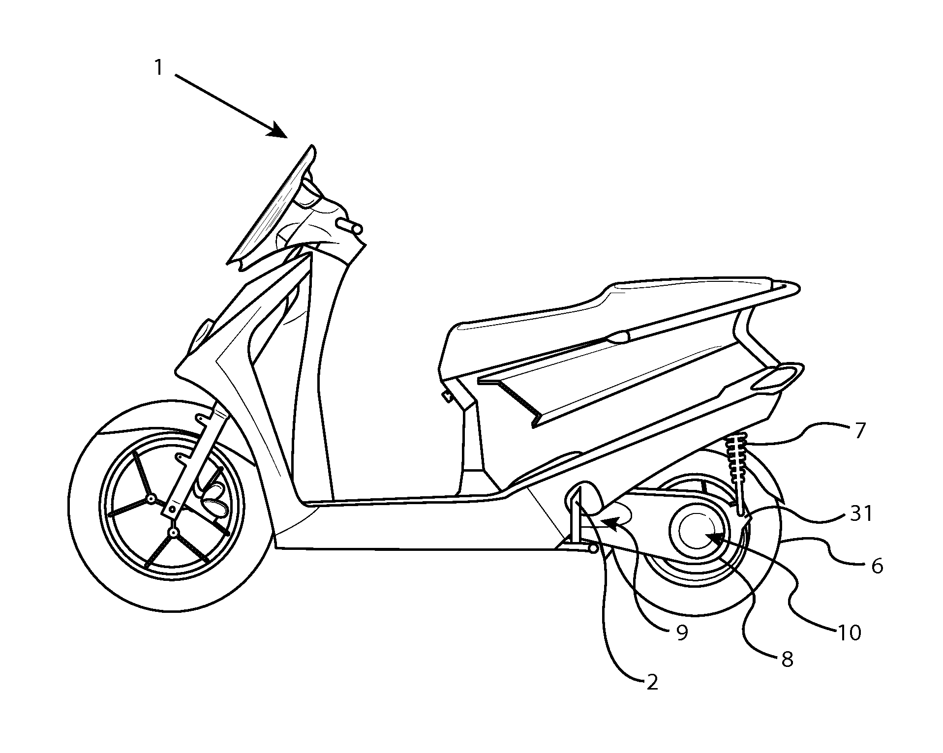
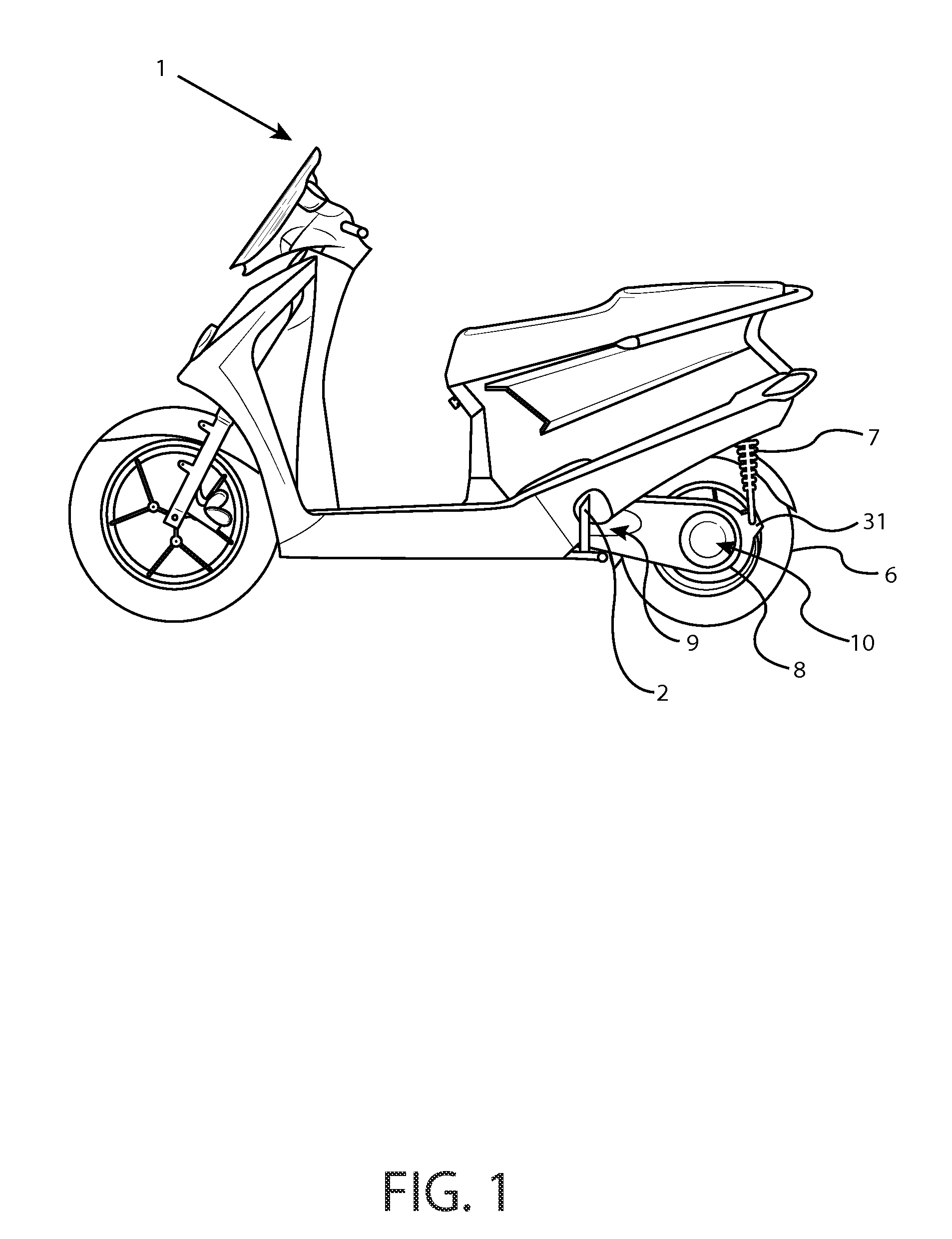
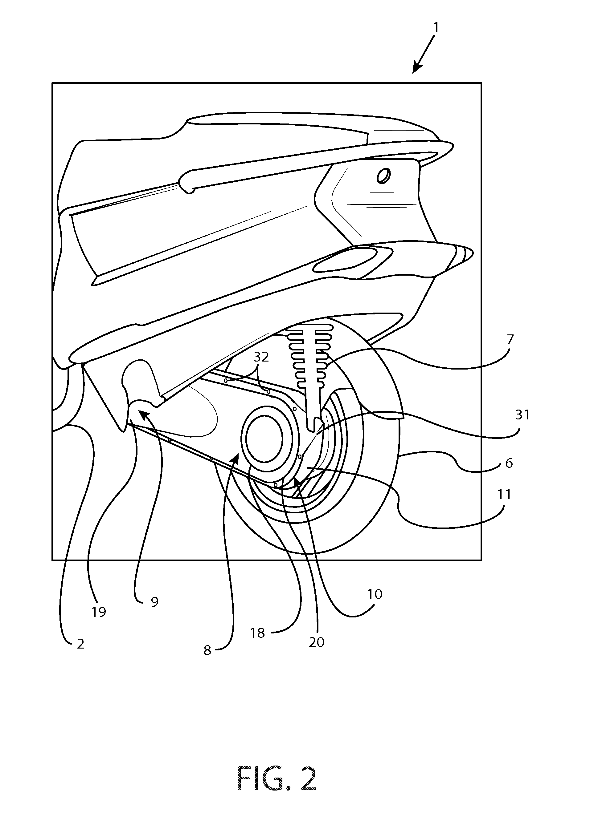
[0027]Referring to FIGS. 1 and 2, disclosed is a ridden motorized vehicle 1 having a monocoque drive enclosure 8. The monocoque drive enclosure having a first end 9 and a second end 10 extending from the main chassis frame 2 of the motorized vehicle 1 to the rear wheel 6 of the motorized vehicle 1. A rear shock absorber 7 may be attached to a shock absorber mount 31 at the second end 10 of the monocoque drive enclosure 8, with the opposite end of the shock absorber mounted to the main chassis frame 2. The shock absorber mount 31 may be integrated into the monocoque drive enclosure 8 or may be separate and attached to the monocoque drive enclosure 8. The shock absorber 7 may be attached to the second end 10 of the drive enclosure 8, as shown in the Figures. Alternatively, the shock absorber 7 may be attached to the drive enclosure 8 at the first end 9 or at some other position along the drive enclosure 8.

[0028]In some embodiments, the shock absorber 7 may be attached to the rear whee...


PUM


Abstract

A ridden motorized vehicle such as a motorized scooter, motorcycle, ATV, tricycle, snowmobile, or lawn tractor, having a driven rear wheel may be equipped with an enclosed chain or belt drive enclosure having a first end and a second end and an inner enclosure and an outer enclosure, such that the inner enclosure has the rear suspension member and the rear wheel mounted at the second end, and concentrically pivots at the first end on the motor assembly output shaft of a motor assembly fastened to or comprising part of the main vehicle frame, and the outer enclosure pivoted on another bearing co-linear with the motor assembly output shaft, but mounted on a removable section of, or attachment to, said frame.

Description


Claims


Application Information

Patent Timeline
Owner HERO MOTOCORP
Learn More