
Vehicle body vibration damping control device

a control device and vehicle body technology, applied in the field of vehicle body vibration damping control devices, can solve the problems of increasing the inability to suppress vibration, and the increase in the comfortablity of the vehicle driving, so as to relieve the fatigue of the driver and improve the comfortability

Active Publication Date: 2013-06-27
NISSAN MOTOR CO LTD
View PDF3 Cites 8 Cited by
  • Summary
  • Abstract
  • Description
  • Claims
  • Application Information

AI Technical Summary

Benefits of technology

The present invention is a vehicle body vibration damping control device which prioritizes the suppression of pitching vibration over bouncing vibration to improve driving comfort and reduce fatigue. This is achieved by controlling the road wheel braking-or-driving force to correct the vehicle body vibrations. The suppression of pitching vibration is set to be higher priority, preventing insufficient suppression and worsening of vehicle comfortability and driver fatigue. The device is easy to implement, low-cost, and has a simple structure.

Problems solved by technology

The pitching vibration from among the vehicle body vibrations has a tendency of enlarging a line of sight movement of a vehicle driver so that a large influence is given to a vehicular comfortablity and to fatigue of the vehicle driver.
Therefore, such a problem is raised that the pitching and bouncing vibrations cannot be suppressed at predetermined priority levels and, due to an insufficient suppression of the pitching vibration, the line of sight movement of the driver becomes large so that the worsening of the vehicular driving comfortablity and the fatigue of the driver are enlarged.
The structure cannot help being complicated.
Hence, it is not actual practice due to its excessively high cost, in any case.

Method used


Image

  • Vehicle body vibration damping control device
  • Vehicle body vibration damping control device
  • Vehicle body vibration damping control device

Examples


Embodiment Construction

[0025]Hereinafter, detailed description of a preferred embodiment according to the present invention will be described in details on a basis of the preferred embodiment shown in the drawings.

Structure of the Preferred Embodiment

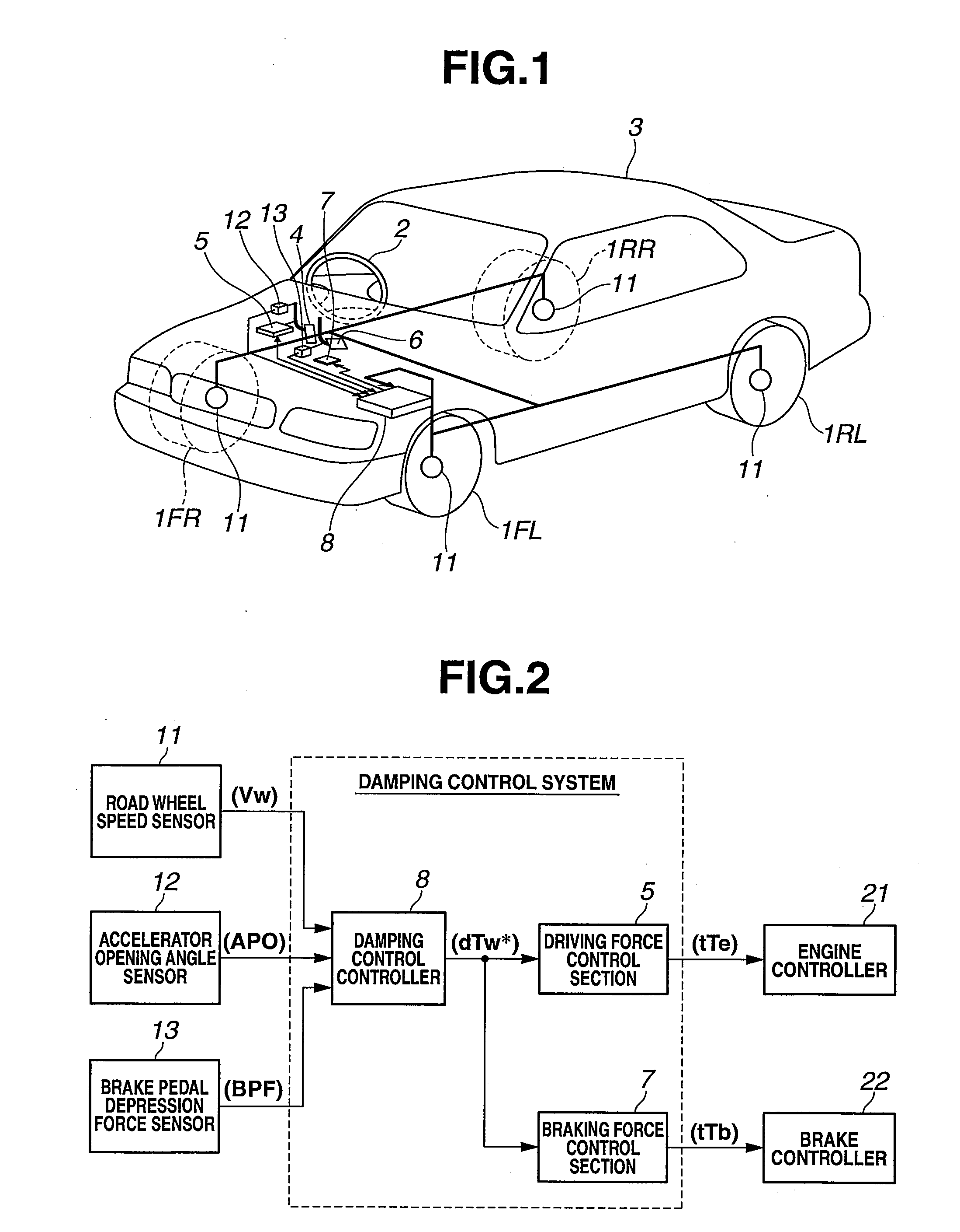
[0026]FIGS. 1 and 2 are rough configuration views representing a vehicle body vibration damping control device which is the preferred embodiment according to the present invention. In FIG. 1, 1FL, 1FR denote left and right front road wheels and 1RL, 1RR denotes left and right rear road wheels. Left and right front road wheels 1FL, 1FR are steered wheels steered (turned) by means of a steering wheel 2. In addition, left and right front road wheels 1FL, 1FR and left and right rear road wheels 1RL, 1RR are suspended on a vehicle body 3 via a suspension unit not shown. This vehicle body 3 is placed at a more upper position than the suspension unit and constitutes a sprung mass.

[0027]An engine not shown as a power source is mounted in a vehicle shown in FIG. 1 so ...


PUM


Abstract

In a vehicle body vibration damping control device, a priority level setting section is configured to set priority levels of a pitching vibration of a vehicle body which is a sprung mass and a bouncing vibration thereof to take a higher priority for a suppression of the pitching vibration between the pitching vibration and the bouncing vibration and a damping purpose braking-or-driving force correction quantity calculation section configured to determine a damping purpose braking-or-driving force correction quantity to suppress vehicle body vibrations on a basis of the pitching vibration and the bouncing vibration, while satisfying the priority levels set by the priority level setting section, to contribute onto a corrective control of a road wheel braking-or-driving force.

Description

TECHNICAL FIELD[0001]The present invention relates to a vehicle body vibration damping control device for suppressing vehicle body vibrations including a pitching vibration and a (vertical) bouncing vibration of the vehicle body which is a sprung mass of the vehicle on which road wheels are suspended via a suspension unit through a corrective control of a road wheel braking-or-driving force.BACKGROUND ART[0002]A patent document 1 exemplifies a conventional vehicle body vibration damping control device.[0003]In this vehicle body vibration damping control technique, a vibration of a vehicle body which is a sprung mass of a suspension unit is estimated from a braking-or-driving torque and road wheel speeds, a braking-or-driving force correction quantity to suppress this vehicle body vibration is determined so that a vibration damping of the vehicle body is carried out with braking-or-driving torques for respective road wheels corrected by this correction quantity to perform the vibrati...

Claims


Application Information

Patent Timeline
IPC IPC(8): B60W30/02B60W10/184B60W10/06
CPCB60W10/06B60W10/184B60W2600/00B60W2520/16B60W2720/30B60W30/025B60W10/10B60W2050/0025B60W2520/28B60W2530/16B60W2540/103B60W2540/12B60W2710/0666B60W2710/182B60W2720/16
Inventor MURATA, TOSHIYUKIKOBAYASHI, YOSUKE
Owner NISSAN MOTOR CO LTD
Learn More