Eureka AIR delivers breakthrough ideas for toughest innovation challenges, trusted by R&D personnel around the world.

System and Method for Determining a Communications Schedule for Relay Nodes of a Wireless Relay Network

a wireless relay network and communication schedule technology, applied in the field of system and method for determining communications schedule, can solve the problems of reducing the capacity required by the various communication links, affecting the reliability of the network, so as to reduce interference and reduce interferen

Active Publication Date: 2013-06-27
AIRSPAN IP HOLDCO LLC
View PDF8 Cites 16 Cited by
  • Summary
  • Abstract
  • Description
  • Claims
  • Application Information

AI Technical Summary

Benefits of technology

The patent text describes a method for generating multiple resource allocations for a wireless network based on real-time data requirements. These resource allocations are determined based on communication limitations that reduce the number of possible options. The method also suggests using directional antennae to reduce interference between multiple communication links and improve the overall efficiency of the network. The technical effect of this approach is an improved resource allocation system for wireless networks that optimizes data transmission and reduces interference.

Problems solved by technology

Through the use of such a relay network, transmitting and recipient nodes are able to communicate with each other even when they are separated by a distance which would otherwise preclude such communication, due for example to an unacceptable level of attenuation of the signal if a direct communication were attempted between the nodes.
However, whilst such an approach enables data to be transmitted over much larger distances than the earlier-described single-hop approach, the capacity required by the various communications links varies significantly.
In many implementations, it can be very difficult to provide the required capacity over such a communications link to ensure reliable communication between all transmitting node / recipient node pairs.

Method used


Image

  • System and Method for Determining a Communications Schedule for Relay Nodes of a Wireless Relay Network
  • System and Method for Determining a Communications Schedule for Relay Nodes of a Wireless Relay Network
  • System and Method for Determining a Communications Schedule for Relay Nodes of a Wireless Relay Network

Examples


Embodiment Construction

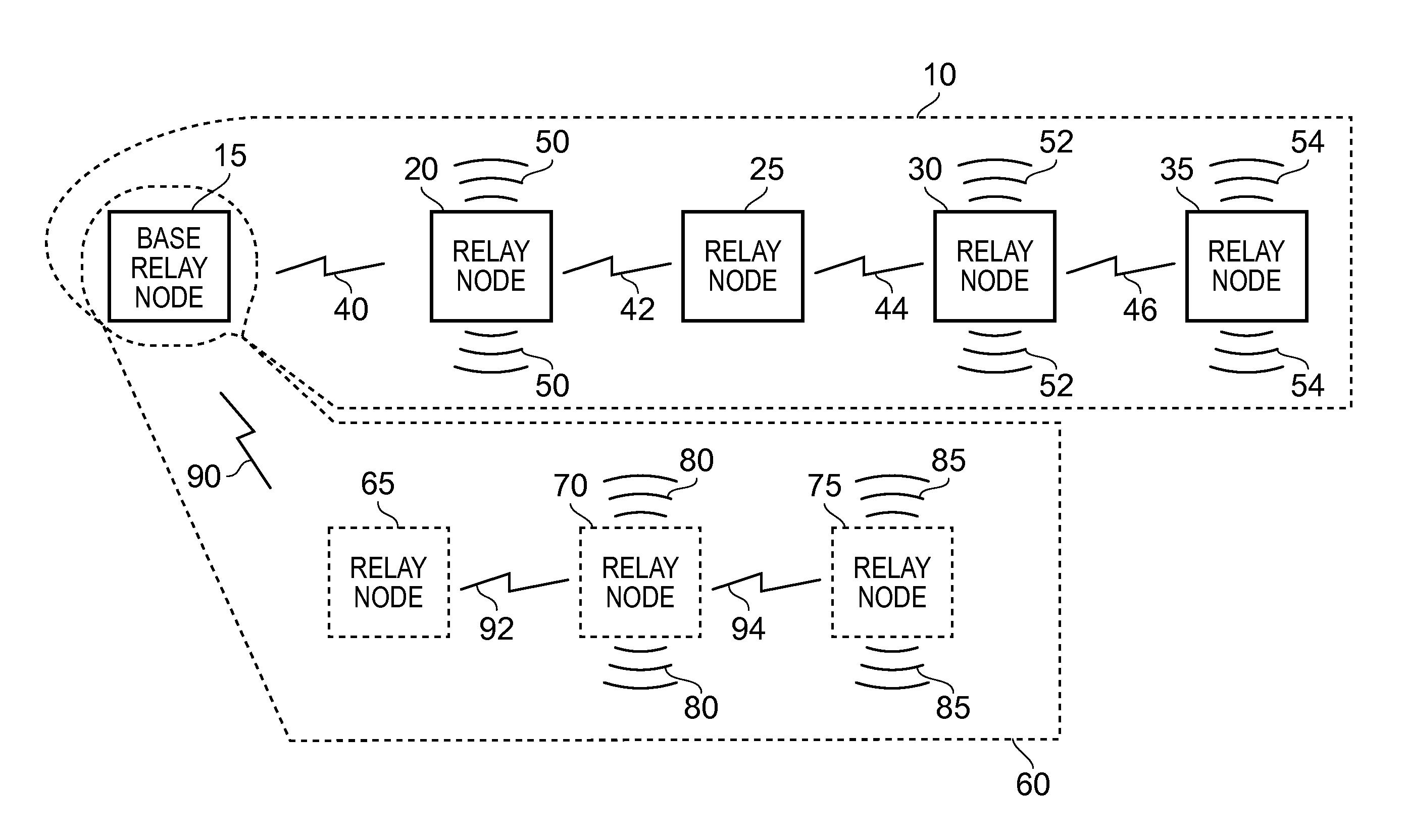
[0060]FIG. 1 schematically illustrates a wireless relay network in which the techniques of embodiments of the present invention may be employed. The wireless relay network shown in FIG. 1A provides a first relay 10 consisting of a base relay node 15 and various other relay nodes 20, 25, 30, 35. In accordance with the techniques of embodiments of the present invention to be described in more detail with reference to the remaining figures, a communications schedule is established between the various relay nodes of the relay 10, the communications schedule interconnecting the plurality of relay nodes by an ordered sequence of communications links. These communications links are illustrated schematically by the reference numerals 40, 42, 44 and 46 in FIG. 1A. For ease of illustration, the relay nodes within the relay 10 are shown as being interconnected in a multi-hop nearest neighbour configuration, but in accordance with the techniques of embodiments of the present invention, the vari...


PUM


Abstract

A communications schedule routes data between relay nodes forming a wireless relay network and interconnects relay nodes by an ordered sequence of communications links established over a wireless resource comprising resource blocks. Candidate connectivity patterns for the ordered sequence of communications links and candidate resource allocations are provided. For each candidate connectivity pattern, a level of a performance characteristic is calculated for a selected combination of the candidate resource allocations. Based on a desired level of the performance characteristic, a candidate connectivity pattern and associated selected combination of candidate resource allocations whose calculated level of the performance characteristic meets the desired level, is selected as the communications schedule. In response to a trigger condition, the performance level evaluation process and the selection process are repeated to re-select one of the candidate connectivity patterns and its associated selected combination of candidate resource allocations to be used as the communications schedule.

Description

BACKGROUND OF THE INVENTION[0001]1. Field of the Invention[0002]The present invention relates to a system and method for determining a communications schedule (also referred to as a communications link structure) for relay nodes of a wireless relay network.[0003]2. Description of the Prior Art[0004]Within a wireless network, there will typically be a plurality of nodes that need to communicate with each other, and wireless communications links are established between the various nodes to support such communications. Considering a wireless telecommunications network, for a downlink communication path a transmitting node (for example a base station (BS)) may need to communicate with a plurality of recipient nodes (such as mobile stations (MSs) / items of end user equipment (UEs)). Similarly, for an uplink communication path multiple transmitting nodes (for example MSs / UEs) may need to communicate with a particular recipient node (for example a BS).[0005]A common approach for establishin...

Claims


Application Information

Patent Timeline
Patent Type & Authority Applications(United States)
IPC IPC(8): H04W72/12H04W72/54
CPCH04W72/12H04B7/2606H04W40/22Y02D30/70H04L41/08H04L41/12H04W16/00H04W72/54
Inventor LYSEJKO, MARTINLOGOTHETIS, ANDREW
Owner AIRSPAN IP HOLDCO LLC
Why Eureka
Eureka Blog
Learn More