SURROUNDING AREA MONITORING DEVICE FOR WORK VEHICLE (as amended)

Active Publication Date: 2013-06-27
KOMATSU LTD
View PDF6 Cites 24 Cited by
  • Summary
  • Abstract
  • Description
  • Claims
  • Application Information

AI Technical Summary

Benefits of technology

The present invention is about a device that allows an operator to easily see the location of a work vehicle while it is traveling. The device creates a unique bird's-eye view image that is useful for identifying objects and obstacles in the surrounding area. When the work vehicle is stopped, the device creates the bird's-eye view image using a virtual projection plane that is designed to increase in height as the distance from the work vehicle increases, so that objects appear enlarged in the images. When the work vehicle is in motion, the device creates the bird's-eye view image using a virtual projection plane that has a uniform flat height from the ground surface, so that the distortion of the ground surface is reduced, and the operator can easily recognize the location of the work vehicle. Overall, this device provides a valuable tool for improving safety and efficiency while driving a work vehicle.

Problems solved by technology

Since these types of dump trucks are markedly wider and longer from front to back than typical vehicles, the driver finds it difficult to discern the conditions in the area surrounding the work vehicle using the side mirrors and the like.
However, when the virtual projection plane is a shape that gradually rises in the traveling direction of the vehicle as described above, an object appears distorted at the outer edge portion of the bird's-eye view image.
Therefore, the road around the vehicle also appears distorted in the bird's-eye view image.
As a result, when the vehicle is traveling, there is a problem in that the operator has difficulty in recognizing the location of the vehicle traveling on the road.
This type of problem is especially noticeable in a work vehicle such as an extra-large dump truck and the like since there are a multitude of regions that the operator cannot observe directly in the surrounding area of the work vehicle.

Method used


Image

  • SURROUNDING AREA MONITORING DEVICE FOR WORK VEHICLE (as amended)
  • SURROUNDING AREA MONITORING DEVICE FOR WORK VEHICLE (as amended)
  • SURROUNDING AREA MONITORING DEVICE FOR WORK VEHICLE (as amended)

Examples


Embodiment Construction

[0031]Hereinbelow, embodiments of the present invention will be described with reference to the accompanying drawings. In the following description, “front,”“back,”“left,” and “right” are terms used on the basis of a driver sitting in the driver's seat. Further, “vehicle width direction” and “left and right direction” have the same meaning.

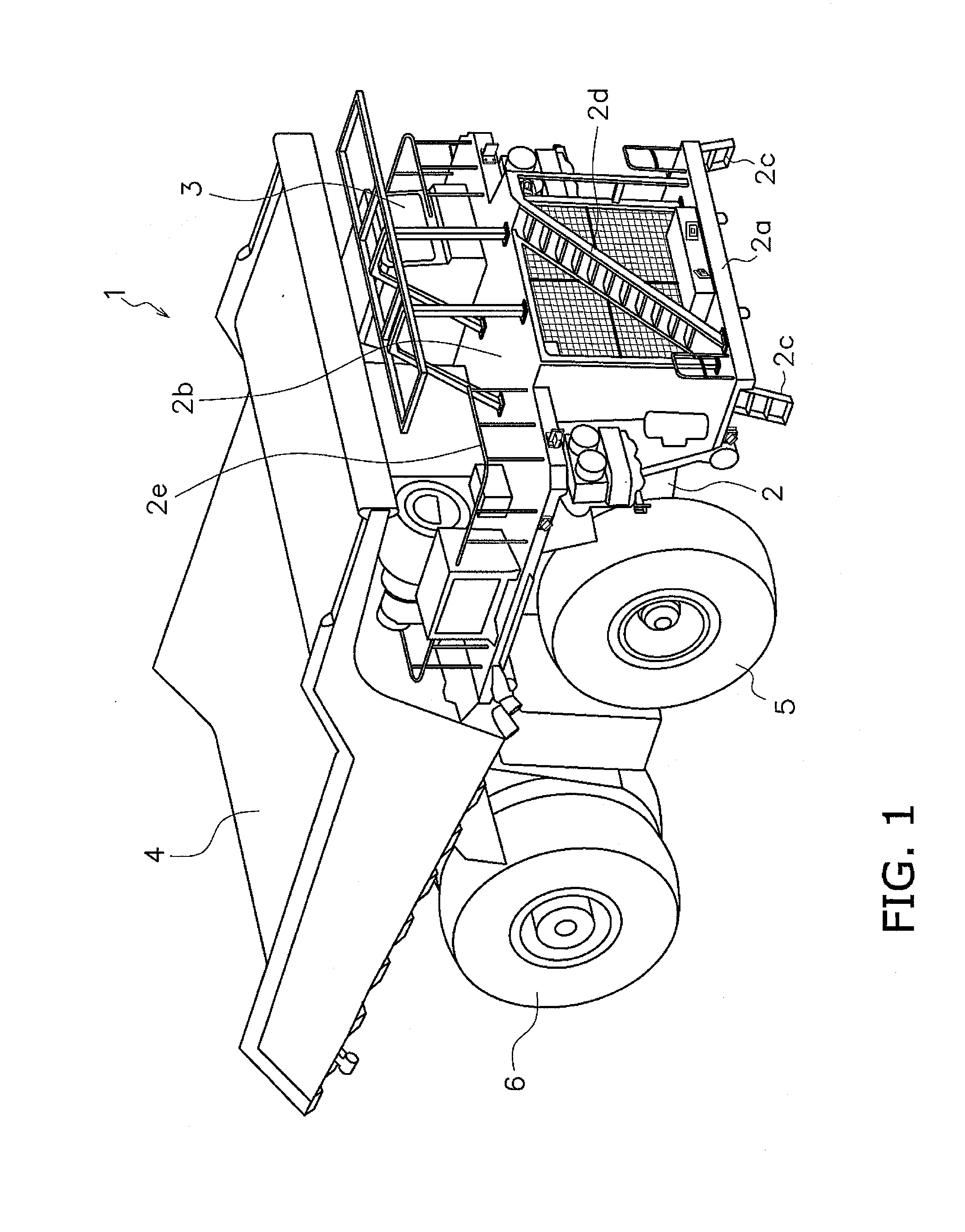
[0032]FIG. 1 is a perspective view of a work vehicle 1 according to an embodiment of the present invention. The work vehicle 1 is a self-propelled extra-large dump truck used in mining operations or the like.

[0033]The work vehicle 1 mainly includes a vehicle frame 2, a cab 3, a vessel 4, front wheels 5, and rear wheels 6. The work vehicle 1 includes a surrounding area monitoring device 10 (see FIG. 2) that monitors a surrounding area of the work vehicle 1 and displays the result. Details of the surrounding area monitoring device 10 are described below.

[0034]The vehicle frame 2 supports power mechanisms such as a diesel engine and a transmission (n...


PUM


Abstract

A work vehicle surrounding area monitoring device includes an imaging unit, a bird's-eye view image creating unit, a display unit and a traveling state determining unit. When the work vehicle is in the stopped state, the bird's-eye view image creating unit is configured to use a first virtual projection plane to create the bird's-eye view image, and at least an outer edge portion of the first virtual projection plane has a shape that increases in height from the ground surface as a distance from the work vehicle increases. When the work vehicle is in the traveling state, the bird's-eye view image creating unit is configured to use a second virtual projection plane to create the bird's-eye view image, and at least an outer edge portion of the second virtual projection plane has a shape having a uniformly flat height from the ground surface.

Description

CROSS-REFERENCE TO RELATED APPLICATIONS[0001]This application claims priority to Japanese Patent Application No. 2011-127307 filed on Jun. 7, 2011, the disclosure of which is hereby incorporated herein by reference in its entirety.TECHNICAL FIELD[0002]The present invention relates to a surrounding area monitoring device for a work vehicle.BACKGROUND ART[0003]Conventionally, trucks as large scale work vehicles are widely used for carrying crushed stone at mines and the like. Since these types of dump trucks are markedly wider and longer from front to back than typical vehicles, the driver finds it difficult to discern the conditions in the area surrounding the work vehicle using the side mirrors and the like.[0004]On the one hand, a surrounding area monitoring device has been proposed for allowing a driver to easily understand the conditions surrounding the vehicle. The surrounding area monitoring device includes an imaging unit such as a camera mounted on the vehicle. The surroundin...

Claims


Application Information

Patent Timeline
IPC IPC(8): H04N7/18
CPCB60R1/00B60R2300/105B60R2300/303E02F9/261B60R2300/607H04N7/18B60R2300/602B60R1/27B60R1/28
Inventor MITSUTA, SHINJIHARADA, SHIGERUTANUKI, TOMIKAZUMASUTANI, EISHINNAKANISHI, YUKIHIROKURIHARA, TAKESHITSUBONE, DAIMACHIDA, MASAOMI
Owner KOMATSU LTD
Why Eureka
Try Eureka