Coupling arrangement for phantom-mode transmission
- Summary
- Abstract
- Description
- Claims
- Application Information
AI Technical Summary
Benefits of technology
Problems solved by technology
Method used
Image

Examples
Embodiment Construction
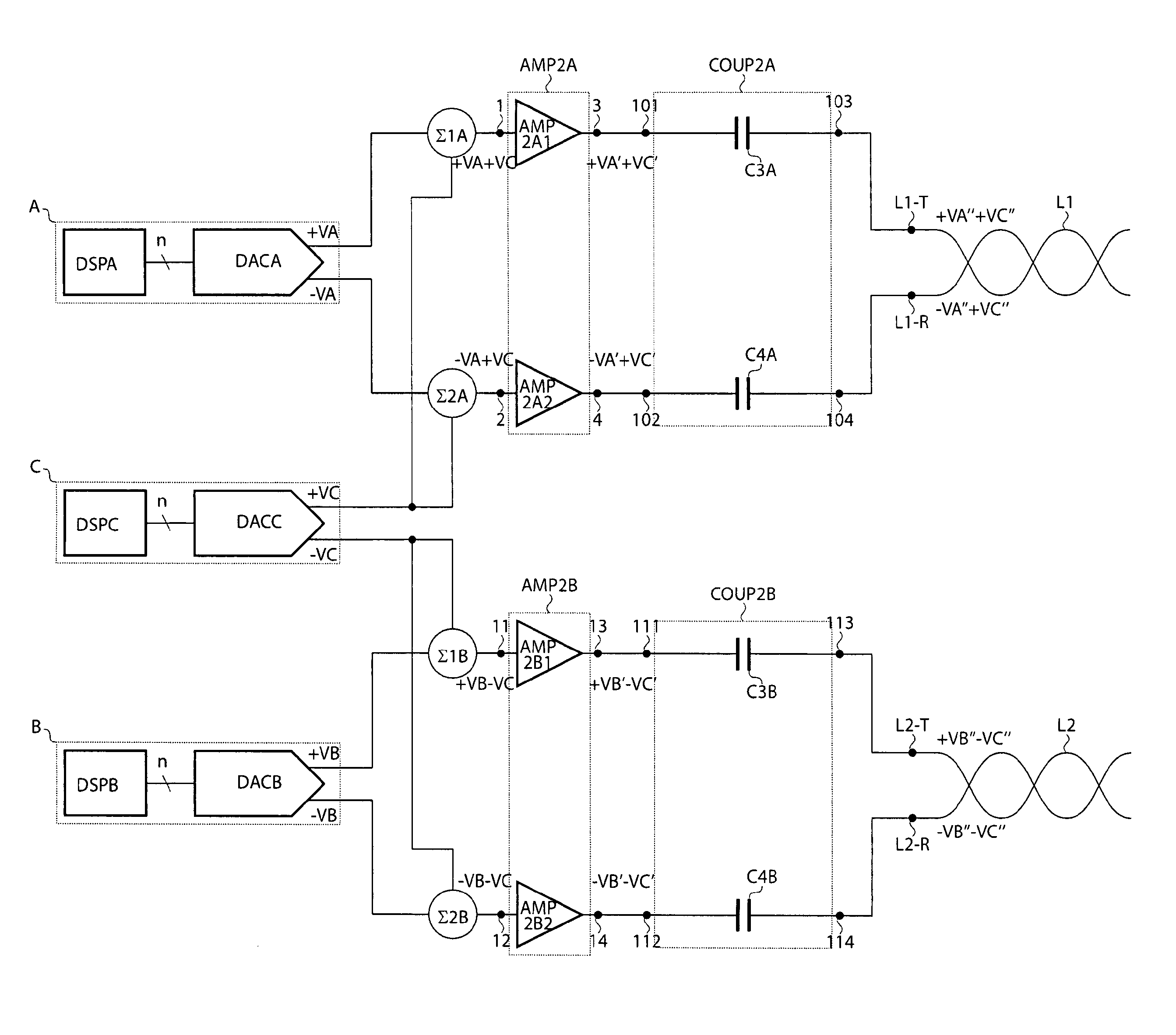
[0042]There is seen in FIG. 3 a first coupling arrangement according to the invention with:
[0043]a first transmit path for coupling a first transmitter A to a first transmission line L1,
[0044]a second transmit path for coupling a second transmitter B to a second transmission line L2, and
[0045]a third transmit path for coupling a third transmitter C for phantom-mode transmission over both lines L1 and L2.
[0046]The coupling arrangement may also comprise corresponding receive paths (not shown) for receiving both differential-mode and common-mode signals from the lines L1 and L2, and for feeding the received signals to respective receivers for further handling (amplifying, demodulating, decoding, etc).
[0047]The three transmitters A, B and C are shown as comprising DSPs DSPA, DSPB and DSPC respectively coupled to DACs DACA, DACB and DACC, but the present invention should not be limited to that specific embodiment and may apply indistinctly to alternative analog or digital transmitter imp...
PUM
 Abstract
Description
Claims
Application Information
 - R&D
- Intellectual Property
- Life Sciences
- Materials
- Tech Scout
- Unparalleled Data Quality
- Higher Quality Content
- 60% Fewer Hallucinations
Browse by: Latest US Patents, China's latest patents, Technical Efficacy Thesaurus, Application Domain, Technology Topic, Popular Technical Reports.
© 2025 PatSnap. All rights reserved.Legal|Privacy policy|Modern Slavery Act Transparency Statement|Sitemap|About US| Contact US: help@patsnap.com