
Expandable Self-Anchoring Interbody Cage for Orthopedic Applications

a self-adjustable, interbody technology, applied in the field of interbody spinal fusion implants, can solve the problems of reducing surgical time, effort, complications, and difficult introduction of current devices into the body, and achieve the effects of maintaining and creating lordosis in the human spine, improving functionality and versatility, and being convenient to us

Active Publication Date: 2013-06-20
BLUE TIP BIOLOGICS
View PDF31 Cites 384 Cited by
  • Summary
  • Abstract
  • Description
  • Claims
  • Application Information

AI Technical Summary

Benefits of technology

The present invention is an interbody cage designed to be used in spinal fusion surgery. It is easier to insert, has fewer parts, and can be expanded and coupled with other interbody cages. It can be introduced into the spine through a minimally invasive approach, and then expanded, anchored, and filled with biologics while in the body. The present invention can be adjusted or removed easily, and it is larger in size and has wider foot print than current devices. Overall, the present invention is more versatile, efficient, and effective in decompressing nerve root and promoting spinal fusion.

Problems solved by technology

Numerous interbody cages have been proposed for use in spinal fusion surgery; however, current devices are difficult to introduce into the body, require many steps for a successful insertion, contain many small parts, cannot be coupled, and are only available in limited sizes.
These features decrease surgical time, effort and complications.

Method used


Image

  • Expandable Self-Anchoring Interbody Cage for Orthopedic Applications
  • Expandable Self-Anchoring Interbody Cage for Orthopedic Applications
  • Expandable Self-Anchoring Interbody Cage for Orthopedic Applications

Examples


Embodiment Construction

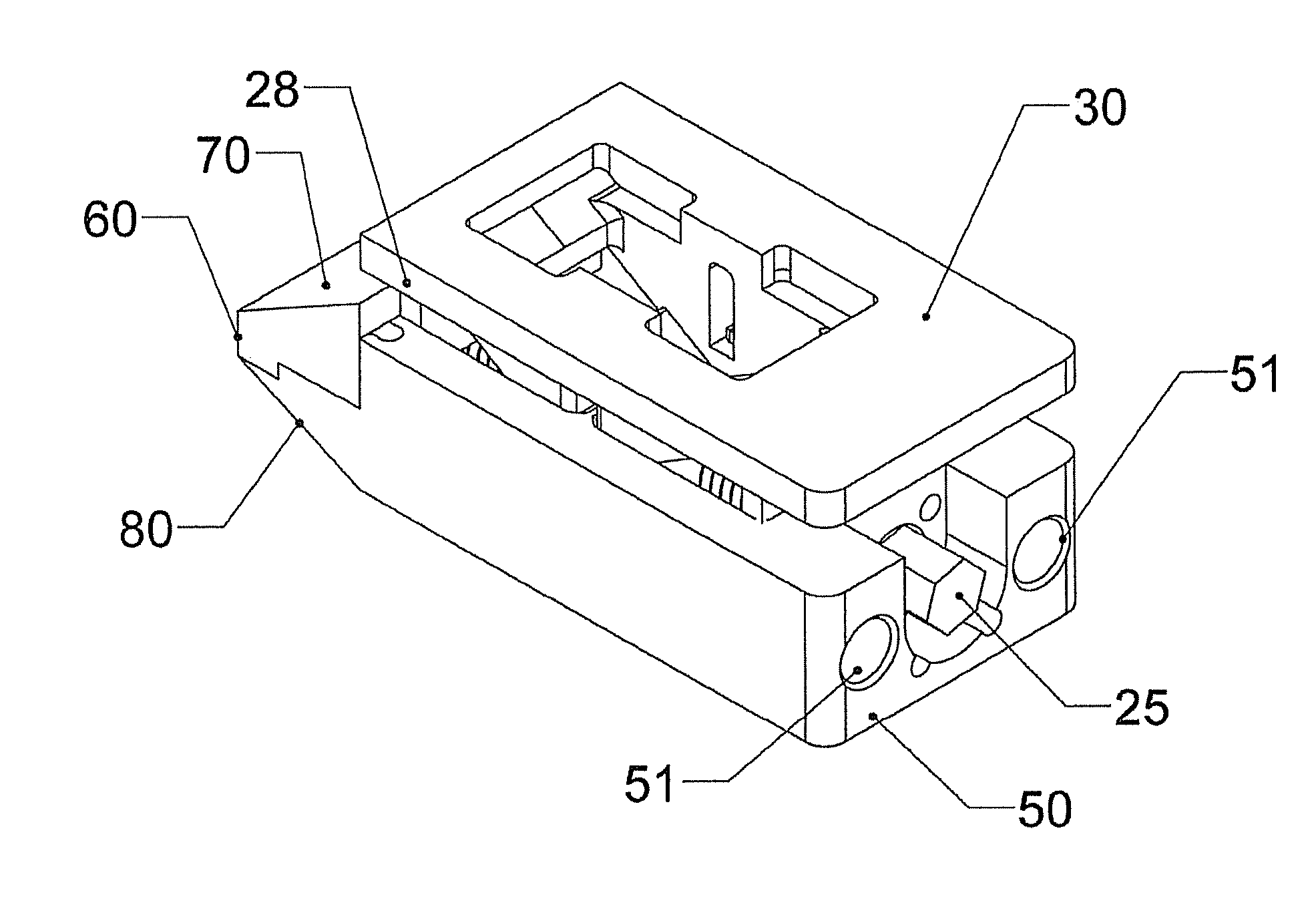
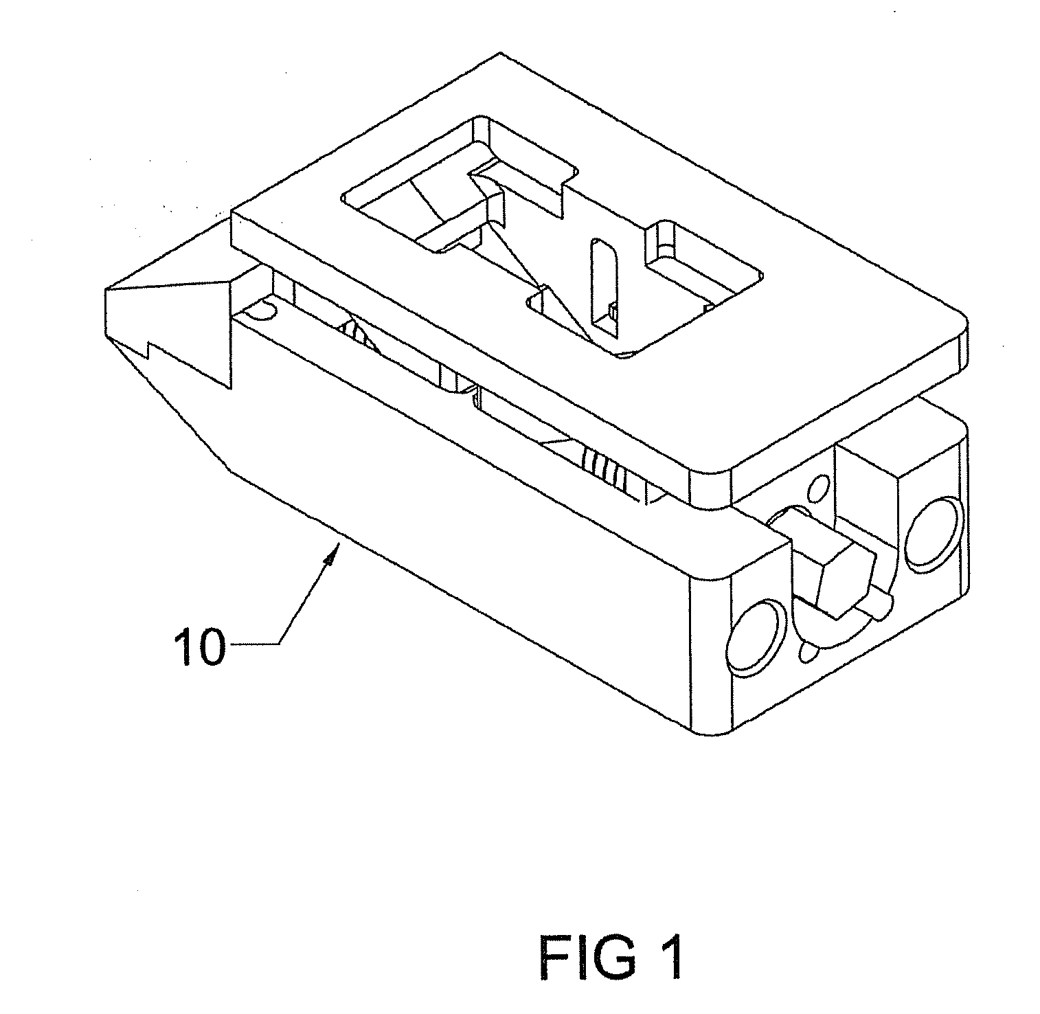
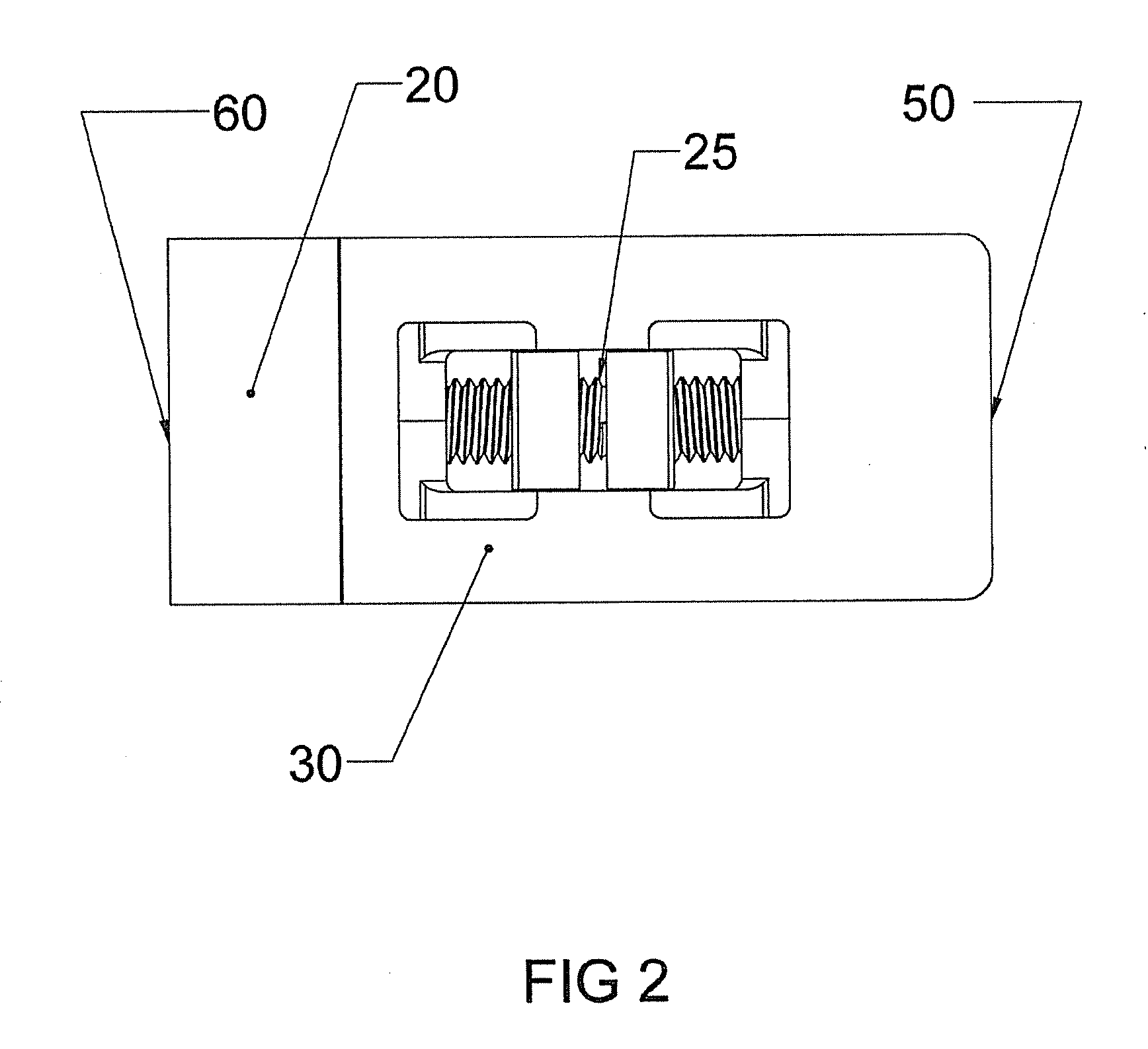
[0076]Various height change mechanisms of the expandable interbody cage 10 can be used to properly space adjacent vertebrae in the spine. Referring to FIGS. 1 through 5, the expandable interbody cage 10 is shown, which generally has a rectangular configuration with a flat top surface 30, a flat bottom surface 40 and a flat leading end 60 bullet nose 20 in a trapezoidal configuration with solid surfaces 60, 70, and 80, as shown in FIGS. 5 and 6. In the preferred embodiment, the top surface 30 is parallel to the bottom surface 40, while the expandable interbody cage 10 is an unexpanded or slightly expanded state, as shown in FIGS. 4 and 5. The top surface 30 and the bottom surface 40 form a support structure for bearing against adjacent vertebrae and when in a fully expanded state commensurate with the needs of a patient, the expandable interbody cage 10 creates an angular relationship is created that maintains the desired lordosis of the human spine. Referring to FIG. 3, in the prefe...


PUM


Abstract

The present invention is directed to an expandable spinal fusion intervertebral implant that provides for maintaining and creating lordosis in the human spine that can be filled with biologics while in situ to encourage spinal fusion. A threaded rod that traverses an insertion / injection handle can be rotated to operate a screw within the interbody cage that displaces opposing vertical tapped sliding wedges, causing them to converge towards each other. Such contact causes the operation of a horizontal wedge that acts as a lift to expand the interbody cage to one of various dimensions in a preferred range. At its desired expansion, the spinal fusion implant of the present invention is sized to fit within the disc space between two vertebral bodies and fill all voids left while the vertical and horizontal wedges operate within, due to the biologics being contained within the interbody cage.

Description

CROSS-REFERENCE TO RELATED APPLICATIONS[0001]The present application is a nonprovisional application of U.S. Provisional Application Ser. No. 61 / 597,865, filed Feb. 13, 2012, the entirety of the disclosure of which is hereby incorporated by reference.STATEMENT OF FEDERALLY SPONSORED RESEARCH OR DEVELOPMENT[0002]Not Applicable.BACKGROUND OF THE INVENTION[0003]1. Field of the Invention[0004]The field of the invention relates generally to interbody spinal fusion implants configured to correct an angular relationship between vertebrae.[0005]2. Description of the Related Art[0006]Implant systems utilizing specially designed spinal instrumentation are often used in surgical procedures concerning spinal conditions. Such implants are used to correct degenerative conditions and facilitate spinal fusion while stabilizing and strengthening the spine. Spinal fusion is the joining of adjacent vertebrae through shared bone. Degenerative conditions which often require spinal fusion surgery include...

Claims


Application Information

Patent Timeline
Patent Type & Authority Applications(United States)
IPC IPC(8): A61F2/44
CPCA61F2/442A61F2/447A61F2002/30772A61F2002/30507A61F2002/30556A61F2002/2835
Inventor SUNGARIAN, ARNOKUSZPA, PHILIPALLEN, W. RILEYCOLE, BRADLEY
Owner BLUE TIP BIOLOGICS
Learn More