Seal arrangement

a technology of sealing arrangement and sealing plate, which is applied in the direction of positive displacement liquid engine, braking system, liquid fuel engine, etc., can solve the problems of reducing the sealing effect, the sealing plate has a rapidly decreasing sealing effect, or the sealing plate has a relatively high wear rate, so as to reduce the wear rate, increase the wear rate, and reduce the effect of sealing

Active Publication Date: 2013-06-20
BURCKHARDT COMPRESSION AG
View PDF5 Cites 14 Cited by
  • Summary
  • Abstract
  • Description
  • Claims
  • Application Information

AI Technical Summary

Benefits of technology

The seal arrangement in this patent has two continuous sealing rings that are held in a common ring carrier and can displace in opposite directions for wear compensation. The sealing rings have no incision or gap, which increases their stiffness and reduces wear. The sealing rings also do not require any elastic or plastic deformability for wear compensation. The ring carrier is designed to hold the sealing rings in a mutually spaced apart position, and a spacer ring is used to separate the rings. The spacer ring can exert a sealing function and acts as a pressure-relieving function for the sealing rings. The sealing rings are guided in a lateral direction by the spacer ring. Overall, this seal arrangement has the advantage of being designed favorably and reliably.

Problems solved by technology

These segments are subject to wear during operation, with the segmentation of the sealing ring having the consequence that the contact pressure of the segments on the piston rod, and thus the sealing effect, is maintained up to a predefined wear limit despite the wear thanks to a self-adjustment of the segments.
The load has the consequence that this seal arrangement has a rapidly decreasing sealing effect and that a flow or a break failure of the seal arrangement respectively occurs in dependence on the material used for the sealing rings.
Known seal arrangements thus have the disadvantage that they may have a rapidly decreasing sealing effect or a relatively high wear under certain circumstances.

Method used


Image

  • Seal arrangement
  • Seal arrangement
  • Seal arrangement

Examples


Embodiment Construction

[0008]It is the object of the invention to form an economically more advantageous seal arrangement.

[0009]This object is satisfied by a seal arrangement having the features of claim 1. Dependent claims 2 to 19 disclose further advantageous embodiments. This object is further satisfied by a seal arrangement having the features of claim 20. Dependent claims 21 to 29 disclose further advantageous embodiments.

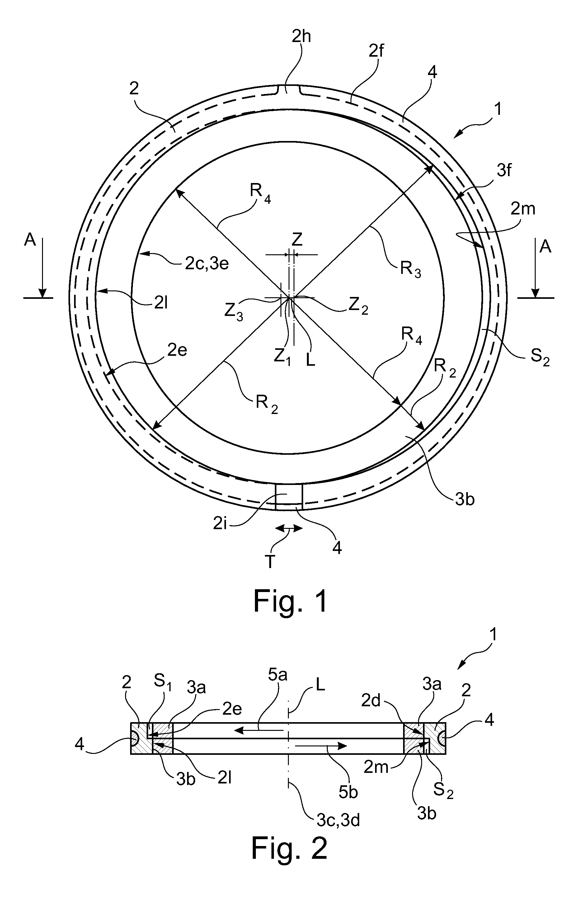
[0010]The object is in particular satisfied by a seal arrangement comprising a deformable ring carrier as well as comprising a first and a second continuous sealing ring, wherein the ring carrier has a longitudinal axis extending perpendicular to its peripheral direction, and wherein the ring carrier has a gap with clearance in its peripheral direction, and wherein each sealing ring has a longitudinal axis extending perpendicular to its peripheral direction, and wherein the sealing rings are arranged such that the ring carrier surrounds them from the outside, and wherein the two sea...


PUM

PropertyMeasurementUnit
Lengthaaaaaaaaaa
Timeaaaaaaaaaa
Angleaaaaaaaaaa

Abstract

The seal arrangement (1) for piston compressors comprises a deformable ring support (2) and a first and a second endless sealing ring (3a, 3b), wherein the ring support (2) has a longitudinal axis (L) which extends perpendicularly with respect to its circumferential direction, and wherein the ring support (2) has a gap (2i) with play in its circumferential direction, and wherein each sealing ring (3a, 3b) has a longitudinal axis (3c, 3d) which extends perpendicularly with respect to its circumferential direction, and wherein the sealing rings (3a, 3b) are arranged in such a way that the ring support (2) encloses them from the outside, and wherein the two sealing rings (3a, 3b) are arranged next to one another in the direction of extent of the longitudinal axis (L), and wherein the ring support (2) and the sealing rings (3a, 3b) are designed to be adapted to one another in such a way that the first sealing ring (3a) bears on one side against a first side wall (2d) of the ring support (2) and forms a first gap (S1) to the ring support (2) on the opposite side with regard to the longitudinal axis (3c) of the first sealing ring (3a), and wherein the second sealing ring (3b) bears in a diametrically opposed manner on one side against a second side wall (21) of the ring support (2) and forms a second gap (S2) to the ring support (2) on the opposite side with regard to the longitudinal axis (3d) of the second sealing ring (3b), wherein the first and second side walls (2d, 21) are arranged so as to lie opposite one another with regard to the longitudinal axis (L), with the result that the ring support (2) can in each case bring about a prestressing force (5a, 5b) on the first and second sealing rings (3a, 3b) respectively via the first and second side walls (2d, 21) respectively, wherein the prestressing forces (5a, 5b) extend in an opposed manner.

Description

[0001]The invention relates to a seal arrangement for piston compressors.PRIOR ART[0002]It is known to seal the piston rod of crosshead piston compressors movably supported in an oscillating manner with the aid of dry-running or lubricated friction sealing elements. The seal along the piston rod takes place via so-called packings which are usually structured in the form of a serial connection of single-part or multipart sealing elements.[0003]The different variants of packings with seal arrangements can roughly be divided into seal arrangements with single-part sealing rings and with multipart sealing rings.[0004]Document WO 97 / 00397 discloses a multipart sealing ring which comprises three segments. These segments are subject to wear during operation, with the segmentation of the sealing ring having the consequence that the contact pressure of the segments on the piston rod, and thus the sealing effect, is maintained up to a predefined wear limit despite the wear thanks to a self-ad...

Claims


Application Information

Patent Timeline
IPC IPC(8): F16J9/06F16J9/16
CPCF16J15/24F16J15/26F16J15/28F16J15/3272F16J15/56F16J9/06F04B53/143F04B39/042F16J9/10F16J15/181F16J9/22F16J9/28F16J9/16
Inventor FEISTEL, NORBERT
Owner BURCKHARDT COMPRESSION AG
Why Eureka
Try Eureka