
Enhancing image data

a technology of image data and image quality, applied in the field of image processing, can solve the problems of poor visibility in bad weather, not always true, and the reliability of these processes degrades rather quickly as the image quality declines

Active Publication Date: 2013-06-06
NAT ICT AUSTRALIA
View PDF2 Cites 28 Cited by
  • Summary
  • Abstract
  • Description
  • Claims
  • Application Information

AI Technical Summary

Benefits of technology

This patent describes a method for estimating the depth of an image using optical information. The method takes into account the optical depth of each point in the image, resulting in a more accurate estimate compared to using a global optical depth estimate. The method can be used without any knowledge of the image's geometry or user interactions. Additionally, the method can also enhance the depth of certain points in the image and determine the quality metric of those points based on their enhanced version. The technical effects of this patent include improved accuracy and efficiency in estimating image depth and the ability to enhance certain points without affecting the overall quality of the image.

Problems solved by technology

Poor visibility in bad weather is a major problem for many applications of computer vision.
Unfortunately, this is not always true as bad weather introduces noise into image data.
In general, the reliability of these processes degrades rather quickly as image quality decreases.

Method used


Image

  • Enhancing image data
  • Enhancing image data
  • Enhancing image data

Examples


example 1

Where No Reference Image is Available

[0097]In this example, no additional information about the image is available (such as a less noisy image of the scene captured when there was no fog).

[0098]Here for the first cost 60, optical depth values are estimated by trying to match the statistics of the enhanced image to baseline statistics of natural images. Since an image of the scene with less noise should be of higher quality than the captured foggy image, we can estimate the depth of a pixel by determining the distance at which the corrected local image region achieves maximum ‘information’. This strategy will only produce an enhanced image—not an estimate of scene on a clear day.

[0099]In this example we use contrast as a measure of information, although a variety of other metrics could be employed. In this example the contrast metric is calculated using the sum of image gradient magnitudes.

[0100]This example assumes there is significant texture in the image so that values for the con...

example 2

Where a Reference Image is Available

[0130]This example, utilizes an image Lref of the scene captured in good visibility conditions from which a reference depth can be determined.

[0131]For fixed cameras, it's quite easy to record what the scene looks like in clear conditions. For a fixed camera, the enhanced foggy image should appear quite similar to the clear day reference image. As a result, a comparison of the two images can be used to guide the first cost determination 60. Although pan-tilt-zoom cameras are popular for surveillance applications, they often have one or more default orientations, which can be treated as fixed vantage points.

[0132]If the only difference between the reference image and the noisy (i.e. foggy) image is the presence of the fog, each pixel, when enhanced, should be very similar to its equivalent in the reference image. Of course, there are several reasons why an enhanced pixel may differ significantly from the reference image. If the pixel corresponds to...


PUM


Abstract

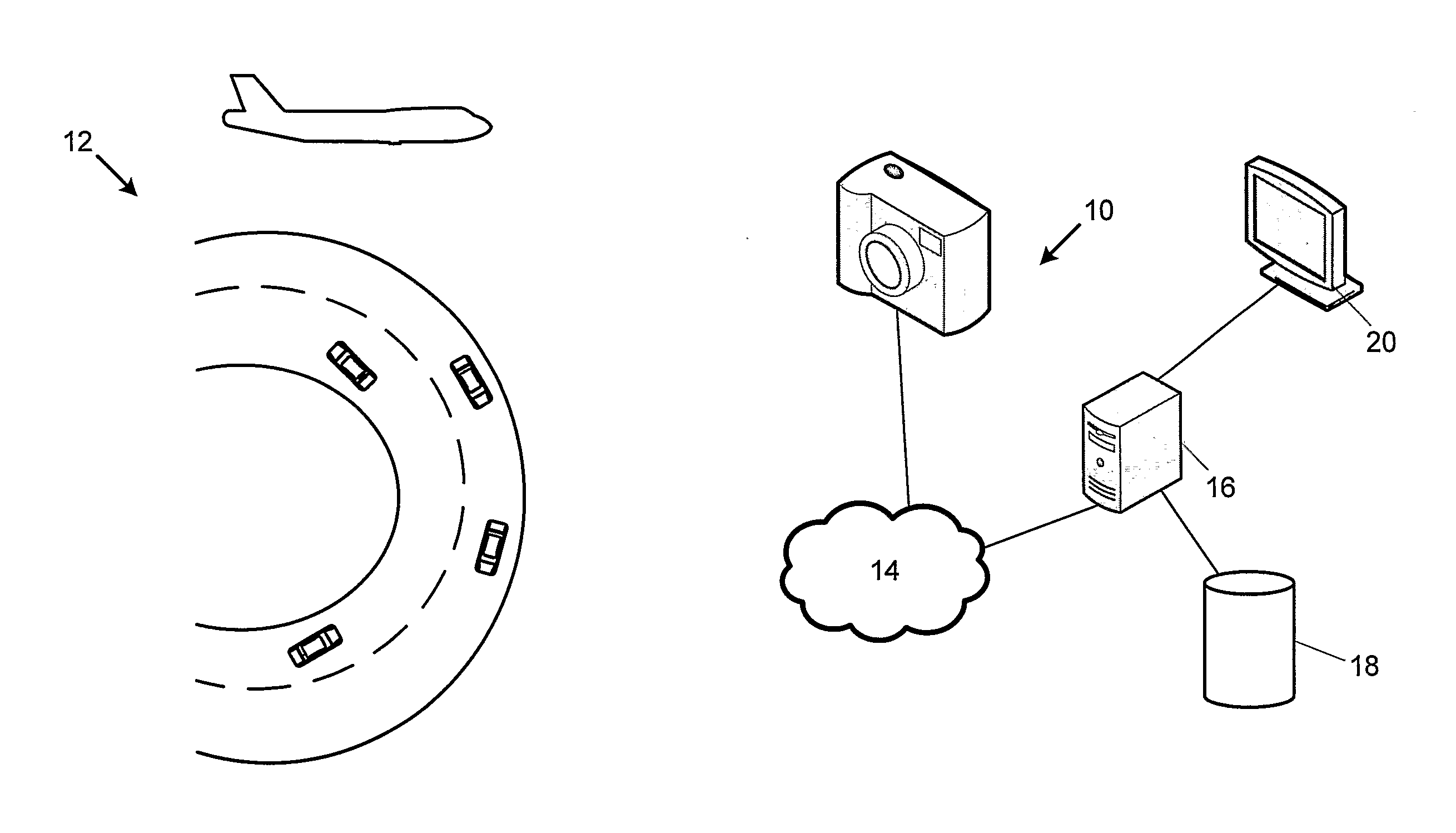
The invention concerns image processing that includes the estimation of the optical depths of points in image data in order to enhance the image data. In particular but not limited to, from the optical depth noise present in the image due to aerosol in the scene, such as fog or haze, can be reduced. The invention concerns determining.a first cost for each point independently based on a determined metric (60) and then a second cost based on an expected correlation in neighbouring points (70). The two costs are then optimized (80) to determine an estimated optical depth for each point (80) that is then used to reduce the effect of aerosol in the image (84). Applications of the invention include, but is not limited to, surveillance systems so that objects in the scene of the image can be better identified once the image data has been enhanced to reduce the estimated noise. Aspects of the invention include a method, software, computer apparatus and a field programmable gate array.

Description

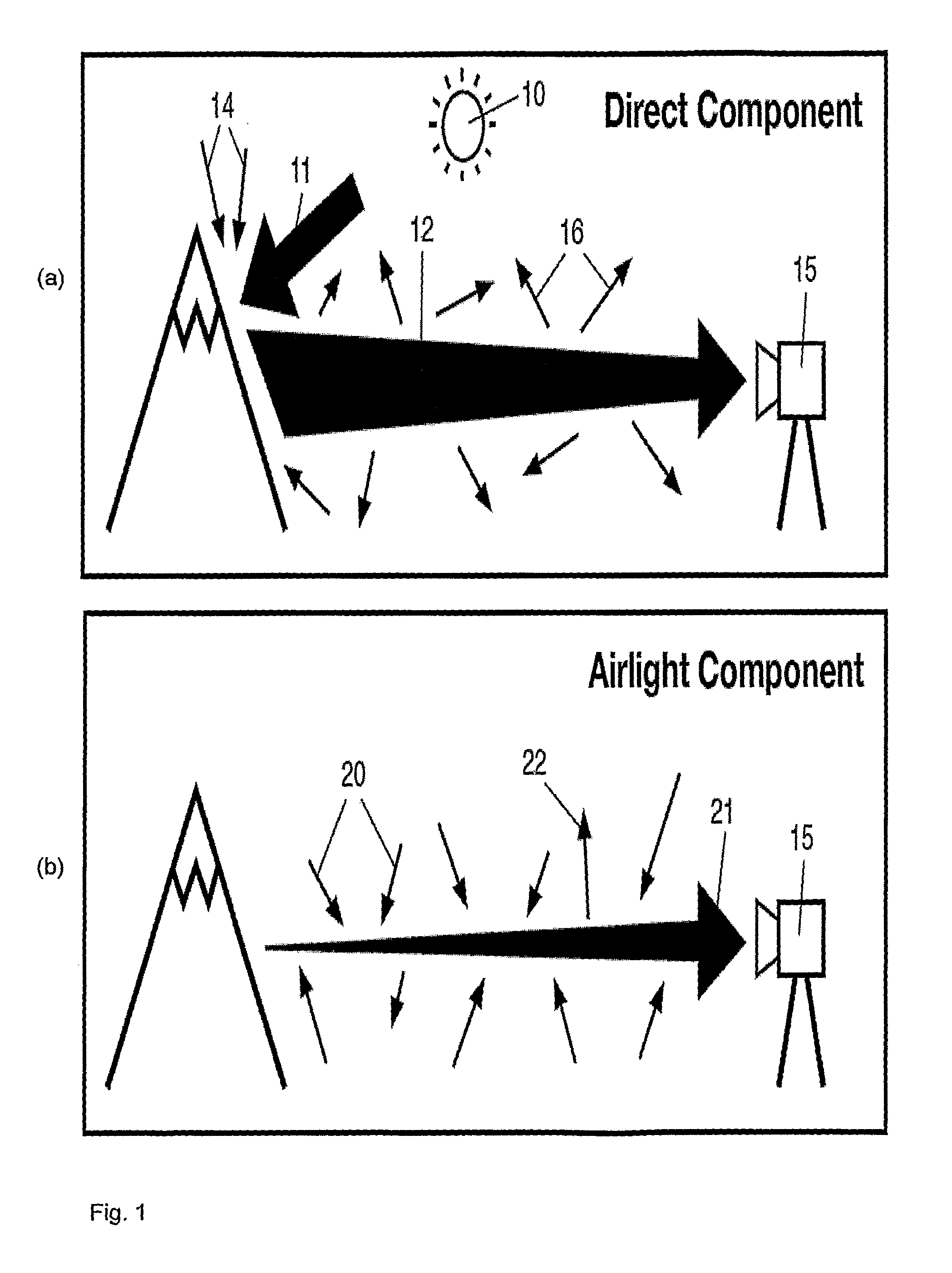
TECHNICAL FIELD[0001]The invention concerns image processing that includes the estimation of the optical depths of points in image data in order to enhance the image data. In particular but not limited to, from the optical depth noise present in the image due to aerosols in the scene, such as fog or haze, can be reduced. Applications of the invention include, but are not limited to, surveillance systems so that objects in the scene of the image can be better identified once the image data has been enhanced to reduce the estimated noise. Aspects of the invention include a method, software, computer apparatus and a field programmable gate array.BACKGROUND OF THE INVENTION[0002]Poor visibility in bad weather is a major problem for many applications of computer vision. Most automatic computer vision systems, such as surveillance, intelligent vehicles, outdoor object recognition, assume that the input images have good visibility. Unfortunately, this is not always true as bad weather intr...

Claims


Application Information

Patent Timeline
Patent Type & Authority Applications(United States)
IPC IPC(8): G06K9/40H04N5/225
CPCG06T2207/30232G06T5/003G06T5/73
Inventor HARTLEY, RICHARDTAN, ROBBYCARR, PETER
Owner NAT ICT AUSTRALIA
Learn More