Speech encoding/decoding device
a technology of encoding/decoding device and speech, which is applied in the field of speech encoding/decoding system, can solve the problems of not being able to obtain a less distorted temporal envelope with respect to the high frequency component, significantly increasing the bit rate of the whole encoded bit stream, etc., to improve the subjective quality of the decoded signal, increase the bit rate, and increase the bit rate
- Summary
- Abstract
- Description
- Claims
- Application Information
AI Technical Summary
Benefits of technology
Problems solved by technology
Method used
Image
Examples
first embodiment
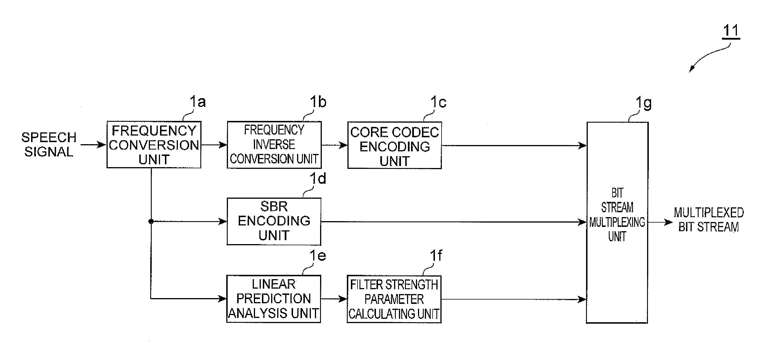
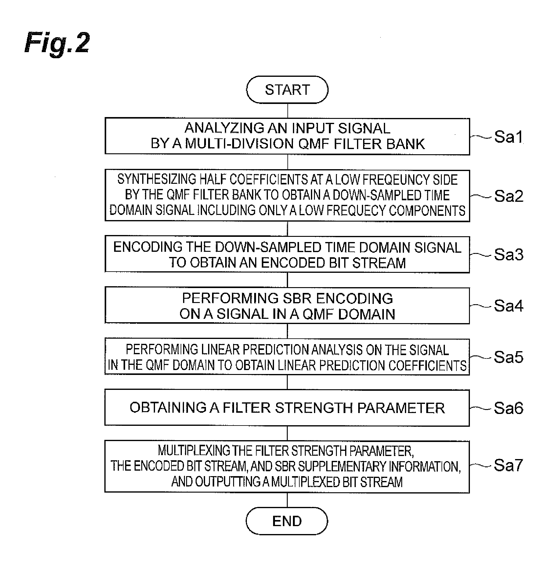
[0099]FIG. 1 is a diagram illustrating an example of a speech encoding device 11 included in the speech encoding / decoding system according to a first embodiment. The speech encoding device 11 may be a computing device or computer, including for example software, hardware, or a combination of hardware and software, as described later, capable of performing the described functionality. The speech encoding device 11 may be one or more separate systems or devices, may be one or more systems or devices included in the speech encoding / decoding system, or may be combined with other systems or devices within the speech encoding / decoding system. In other examples, fewer or additional blocks may be used to illustrate the functionality of the speech encoding device 11. In the illustrated example, the speech encoding device 11 may physically include a central processing unit (CPU) or processor, and a memory. The memory may include any form of data storage, such as read only memory (ROM), or a r...
second embodiment
[0144]FIG. 6 is a diagram illustrating an example speech encoding device 12 according to a second embodiment. The speech encoding device 12 physically includes a CPU, a ROM, a RAM, a communication device, and the like, which are not illustrated, and the CPU integrally controls the speech encoding device 12 by loading and executing a predetermined computer program (such as a computer program for performing processes illustrated in the flowchart of FIG. 7) stored in a memory of the speech encoding device 12 such as the ROM into the RAM, as previously discussed with respect to the first embodiment. The communication device of the speech encoding device 12 receives a speech signal to be encoded from outside the speech encoding device 12, and outputs an encoded multiplexed bit stream to the outside.
[0145]The speech encoding device 12 functionally includes a linear prediction coefficient decimation unit 1j (prediction coefficient decimation unit), a linear prediction coefficient quantizin...
third embodiment
[0158]FIG. 10 is a diagram illustrating an example speech encoding device 13 according to a third embodiment. The speech encoding device 13 physically includes a CPU, a ROM, a RAM, a communication device, and the like, which are not illustrated, and the CPU integrally controls the speech encoding device 13 by loading and executing a predetermined computer program (such as a computer program for performing processes illustrated in the flowchart of FIG. 11) stored in a built-in memory of the speech encoding device 13 such as the ROM into the RAM, as previously discussed. The communication device of the speech encoding device 13 receives a speech signal to be encoded from outside the speech encoding device, and outputs an encoded multiplexed bit stream to the outside.
[0159]The speech encoding device 13 functionally includes a temporal envelope calculating unit 1m (temporal envelope supplementary information calculating unit), an envelope shape parameter calculating unit 1n (temporal en...
PUM
 Abstract
Description
Claims
Application Information
 - R&D
- Intellectual Property
- Life Sciences
- Materials
- Tech Scout
- Unparalleled Data Quality
- Higher Quality Content
- 60% Fewer Hallucinations
Browse by: Latest US Patents, China's latest patents, Technical Efficacy Thesaurus, Application Domain, Technology Topic, Popular Technical Reports.
© 2025 PatSnap. All rights reserved.Legal|Privacy policy|Modern Slavery Act Transparency Statement|Sitemap|About US| Contact US: help@patsnap.com


