Eureka AIR delivers breakthrough ideas for toughest innovation challenges, trusted by R&D personnel around the world.

System for guiding an aircraft to a reference point in low visibility conditions

Active Publication Date: 2013-05-30
ELBIT SYST LTD
View PDF5 Cites 92 Cited by
  • Summary
  • Abstract
  • Description
  • Claims
  • Application Information

AI Technical Summary

Benefits of technology

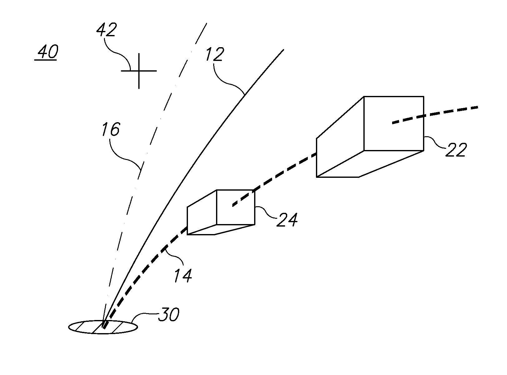
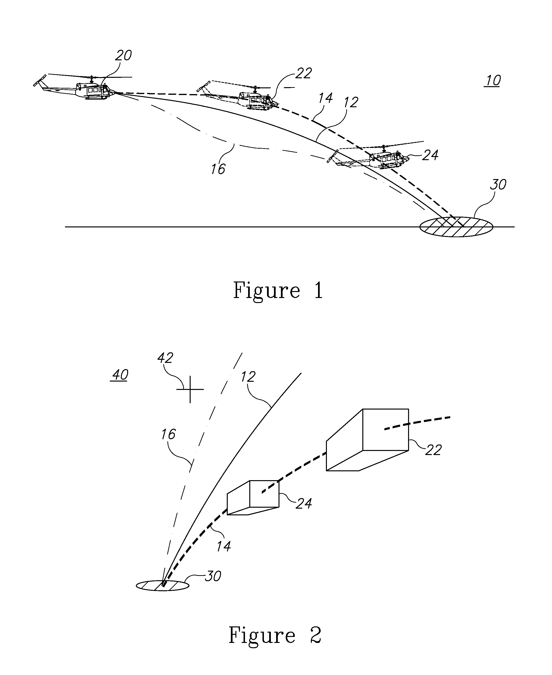
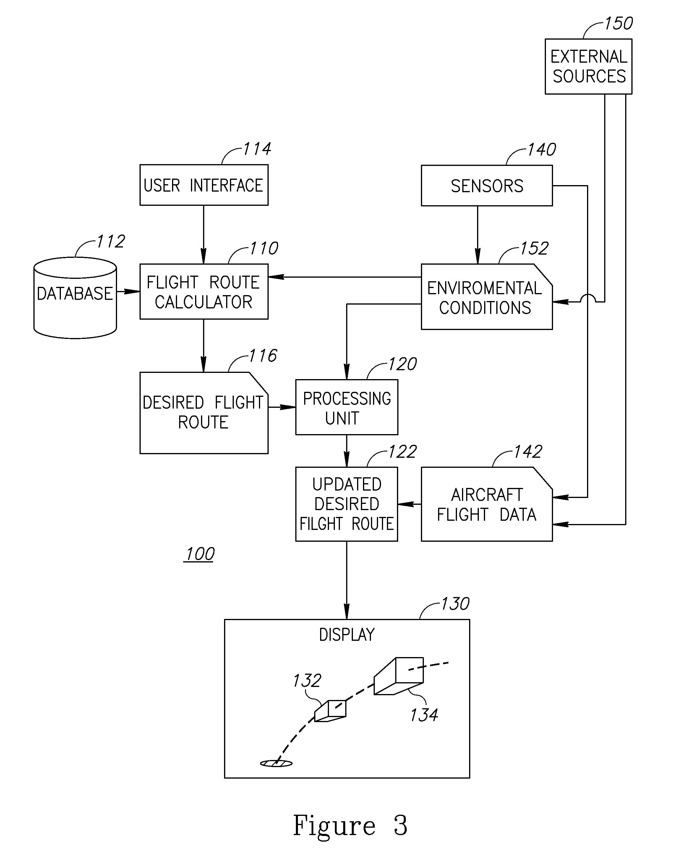
This patent describes a method for guiding a pilot flying an aircraft using visual symbols that change position in real-time. The method involves determining a desired flight path for the aircraft, and then showing a 3D visual symbol on a display that moves along the path. The position of the symbol is continuously updated based on real-time information about the aircraft's location, speed, and angle. This system can be implemented through a computer program or a system of multiple components. The technical effect of this patent is to provide a better way for pilots to visualize and follow the path they need to fly, which can improve safety and efficiency.

Problems solved by technology

Low visibility conditions, usually due to harsh weather or dust, pose a real challenge for pilots in performing various maneuvers such as landing, avoiding obstacles, and following a terrain in low altitude.

Method used


Image

  • System for guiding an aircraft to a reference point in low visibility conditions
  • System for guiding an aircraft to a reference point in low visibility conditions
  • System for guiding an aircraft to a reference point in low visibility conditions

Examples


Embodiment Construction

[0019]Prior to setting forth the detailed description, it may be helpful to set forth definitions of certain terms that will be used hereinafter.

[0020]The term “aircraft” as used herein in this application refers to any air vehicle, be it a rotor propelled aircraft or a fixed-wing aircraft.

[0021]The term “flight data” as used herein in this application refers to any physical data relating to position, speed, acceleration, orientation and the like, that characterize a momentary movement of an aircraft.

[0022]The term “physical flight” as used herein in this application refers to a realistic flight pattern due to laws of physics and limitations imposed by either the performance envelope of a specified aircraft or by safety regulations.

[0023]The term “virtual wingman” as used herein in this application refers to a virtual symbol resembling another aircraft in an aircraft formation which serves as a dynamic point of reference for the pilot, in a way that resembles following a real lead p...


PUM


Abstract

A method of visually guiding a pilot flying an aircraft using one or more conformal symbols whose position is dynamically updated throughout the guidance is provided herein. The method includes the following stages: determining a desired flight route of an aircraft, based on a user-selected maneuver; presenting to a pilot, on a display, at least one 3D visual symbol that is: (i) earth-space stabilized, and (ii) positioned along a future location along the desired route; computing an updated desired route based on repeatedly updated aircraft flight data that include at least one of: location, speed, and spatial angle, of the aircraft; and repeating the presenting of the at least one 3D visual symbol with its updated location along the updated desired route.

Description

BACKGROUND[0001]1. Technical Field[0002]The present invention relates to a visual guiding tool for pilots and more particularly, to such tools that employ conformal symbology.[0003]2. Discussion of the Related Art[0004]Low visibility conditions, usually due to harsh weather or dust, pose a real challenge for pilots in performing various maneuvers such as landing, avoiding obstacles, and following a terrain in low altitude.[0005]Visual guiding tools, for guiding pilots by providing visual reference indicators throughout a specific maneuver are known in the art. One important prerequisite of these tools is that the visual indicators will be conformal with the pilot's view so that he or she may use the visual indicators as references for the actual surrounding.[0006]One notable visual guidance tool is referred to as “virtual pathways in the sky” in which a conformal pathway or series of gates are presented to the pilot. The pathways or the gates serve as points of reference and by foll...

Claims


Application Information

Patent Timeline
IPC IPC(8): G08G5/02
CPCG08G5/0021G08G5/025G08G5/0052
Inventor NAUMAN, RONEFRAT, ILANHARTUV, ROEEHALIFA, EYALKLEIN, OFERMAKOV, HAGAYGALED, ERAN
Owner ELBIT SYST LTD
Why Eureka
Eureka Blog
Learn More