
Image inspection apparatus, image forming apparatus, image inspection method, and image inspection program

a technology of image inspection and forming apparatus, applied in the direction of image enhancement, image analysis, instruments, etc., can solve the problems of contact glass and reference white plate stained with ink, inability to realistically prepare model images, and inability to fully dry ink

Active Publication Date: 2013-05-30
RICOH KK
View PDF17 Cites 17 Cited by
  • Summary
  • Abstract
  • Description
  • Claims
  • Application Information

AI Technical Summary

Benefits of technology

The present invention provides an image inspection apparatus and method for inspecting images output on sheets and transported along a transport route inside the image inspection apparatus. The apparatus includes a reference white plate, contact glass, image scanning device, and noise detector for detecting noise in blank areas of the sheets and reference white plate. The apparatus can identify whether the noise originates from the contact glass or reference white plate, and use this information to determine if there is a stain on the sheets or reference white plate. The technical effect of this invention is the ability to quickly and accurately inspect images on sheets for quality control purposes.

Problems solved by technology

At present, such image inspection capabilities are also desired for printers used for on-demand printing, in which print data may be different for every sheet and consequently it is not realistic to prepare model images.
Further, because the inspection target printed image has just been printed, the ink may not be completely dry by the time image inspection is conducted.
As a result, the contact glass and the reference white plate may be stained with ink where they contact the document sheet.
Stains on the contact glass may get mixed in with the scanned image and appear as noise, thereby degrading scanning precision.
If inspection is conducted under such conditions, it becomes difficult to determine whether a poor inspection result is caused by the poor quality of the inspection target printed image itself or by stains on the contact glass, by which a false inspection or miss-inspection may occur.
Further, because the reference white plate is used as a standard for shading correction in image scanning, stains on the reference white plate may also get mixed with the scanned image as noise.
If shading correction is not conducted effectively due to such stains, both image scanning precision and inspection precision deteriorate.
To conduct such removal, operation of the image inspection apparatus and / or image forming apparatus must be stopped, but if for some reason the image inspection apparatus and / or image forming apparatus cannot be stopped immediately, such stain removal may not be conducted at an appropriate timing.
Further, because the reference white plate is scanned through the contact glass, the low intensity of detection light coming from the reference white plate may be caused by stains on either the contact glass or on the reference white plate; i.e., the stain origin cannot be identified.
However, as above mentioned, because the stain origin cannot be identified when the reference white plate is scanned in the conventional method, such enhanced image inspection is not practical.

Method used


Image

  • Image inspection apparatus, image forming apparatus, image inspection method, and image inspection program
  • Image inspection apparatus, image forming apparatus, image inspection method, and image inspection program
  • Image inspection apparatus, image forming apparatus, image inspection method, and image inspection program

Examples


first example embodiment

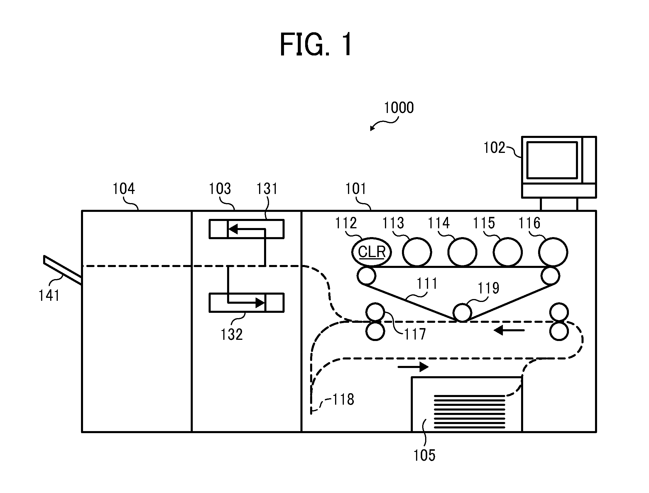
[0038]FIG. 1 shows a schematic configuration of an image forming / inspecting system having an image forming apparatus and an image inspection apparatus according to a first example embodiment. As shown in FIG. 1, an image forming / inspecting system 1000 includes, for example, an image forming apparatus 101, an image inspection apparatus 103, and a stacker 104. The image forming apparatus 101 includes, for example, a control unit 102, and an image forming unit controlled by a printer engine. The image forming unit includes, for example, a sheet feed unit 105, photoconductor drums 112, 113, 114, 115, 116, a transfer belt 111, a transfer roller 119, and a fusing roller 117.

[0039]Sheets can be transported in a direction shown by an arrow along the dotted line in FIG. 1 from the sheet feed unit 105. Toner images of clear (CLR), black (K), cyan (C), magenta (M), and yellow (Y) formed on corresponding photoconductor drums 112, 113, 114, 115, and 116 can be superimposed on the transfer belt 1...

second example embodiment

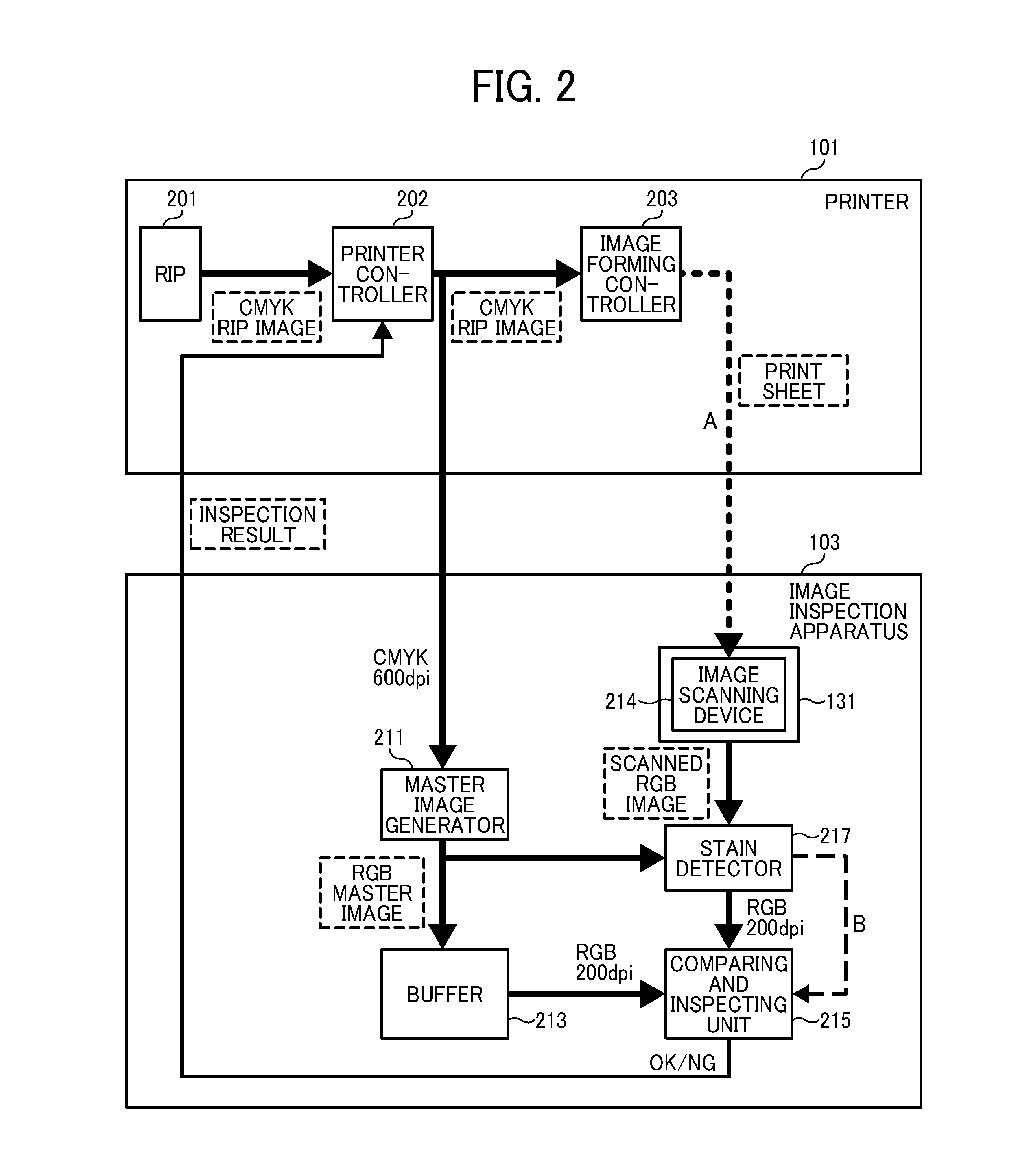
[0116]A description is given of second example embodiment using another configuration that a stain detector cannot receive the master image data wherein the hardware configuration is not changed from the above-described configuration. For ease of understanding, the stain detector used for the second example embodiment is referred to as a stain detector 217A. In such configuration, the stain on the contact glass 702 alone can be detected similar to the above-described configuration using the master image data in the first example embodiment.

[0117]Specifically, in the second example embodiment, as for the scanning on sheet, instead of using the master image data, a blank sheet is passed under the image scanning device 214 to scan a blank area, and a control process adapted for such method is devised so that the stain detection can be conducted similar to the above described configuration using the master image data in the first example embodiment. Such image data obtainable by using t...


PUM


Abstract

An image inspection method and apparatus for inspecting images output on sheets including a reference white plate disposed at a position of the transport route of sheet while facing a scan position for scanning a sheet; a contact glass disposed opposite the reference white plate; an image scanning device fixed facing the scan position to conduct a scanning operation through the contact glass, a noise detector to detect a first noise image in a blank area of the inspection sheet by scanning the blank area of the inspection sheet, and a second noise image in the reference white plate by scanning the reference white plate; and a stain source determination unit to determine a noise origin from the contact glass or the reference white plate.

Description

CROSS-REFERENCE TO RELATED APPLICATIONS[0001]This application claims priority to Japanese Patent Application Nos. 2011-258284, filed on Nov. 25, 2011, and 2012-193500, filed on Sep. 3, 2012 in the Japan Patent Office, which are hereby incorporated by reference herein in their entirety.BACKGROUND[0002]1. Technical Field[0003]The present invention relates to an image inspection apparatus to inspect images formed on sheets of recording media by an image forming apparatus such as a printer, a multi-functional apparatus using image data prepared from print data, an image forming apparatus provided with the image inspection apparatus, an image inspection method, and an image inspection program.[0004]2. Description of the Background Art[0005]Printers or the like form images on recording sheets based on print data. To produce high-quality printed images, the printers may be provided with image inspection apparatuses to inspect the output images.[0006]Conventional image inspection apparatuse...

Claims


Application Information

Patent Timeline
Patent Type & Authority Applications(United States)
IPC IPC(8): G06K9/00G06V30/40
CPCG06K9/00442G06T5/00G06T7/0002G06T2207/30144G06K9/00483G06T7/001G06V30/40G06V30/418
Inventor KAWAMOTO, HIROYUKI
Owner RICOH KK
Learn More