
Multi-touch input device

a multi-touch input and input device technology, applied in the field of multi-touch input devices, can solve the problems of greatly impairing game play, inability to import prevent the migration of most popular console and pc games. , to achieve the effect of preventing the migration of most popular console and pc games, facilitating rapid and easy selection of submenus and items

Inactive Publication Date: 2013-05-16
MAUS DARYL D
View PDF6 Cites 149 Cited by
  • Summary
  • Abstract
  • Description
  • Claims
  • Application Information

AI Technical Summary

Benefits of technology

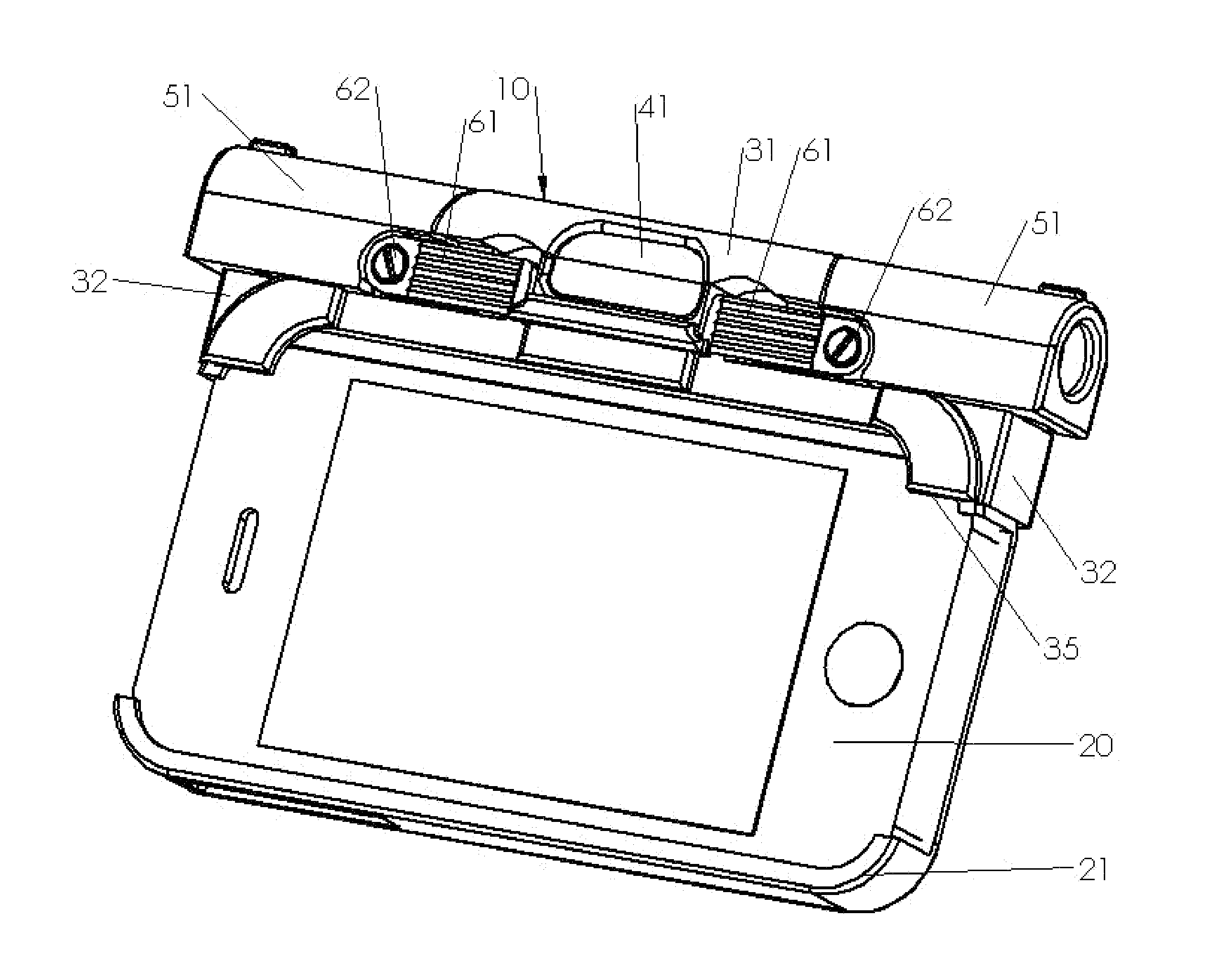
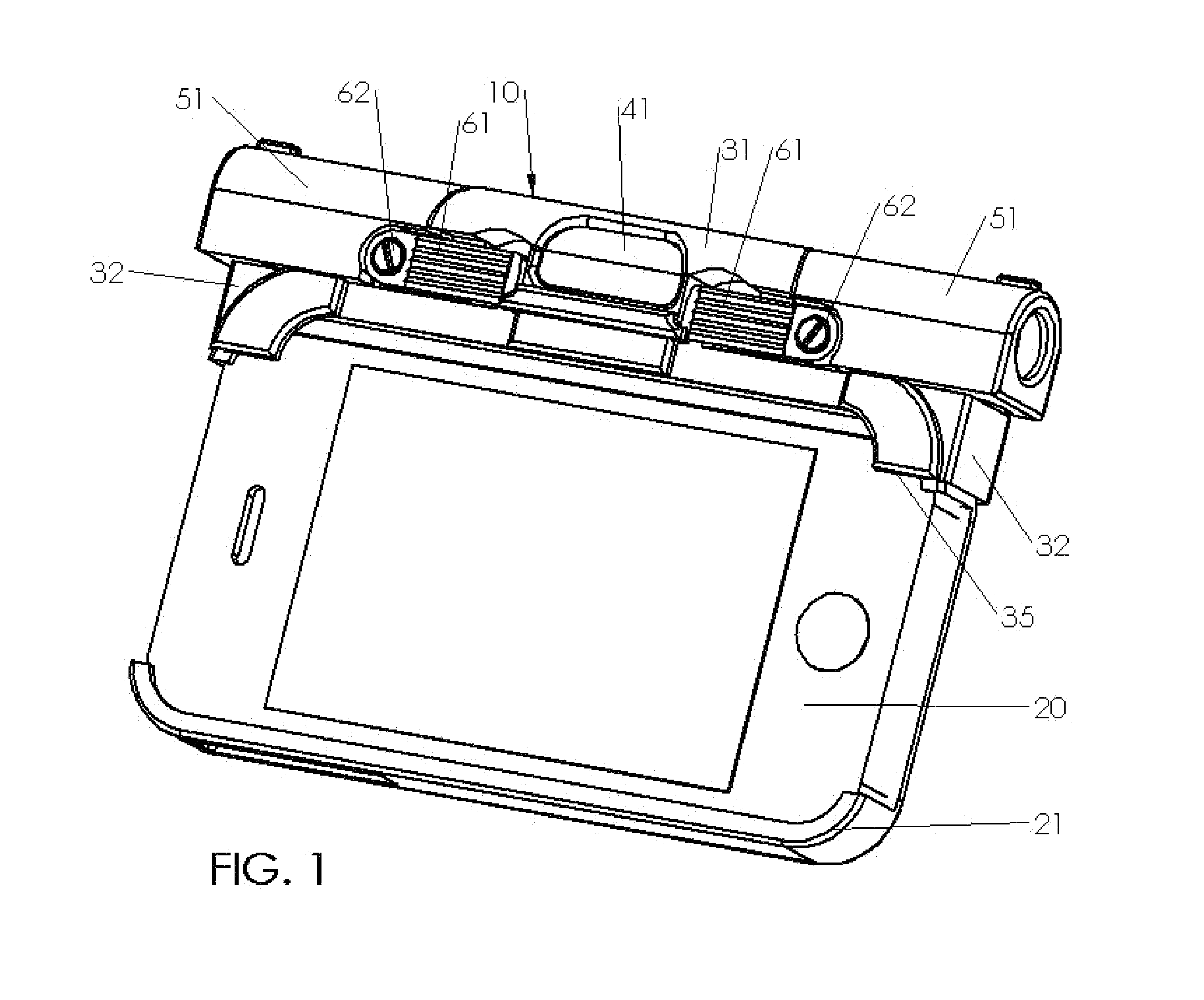
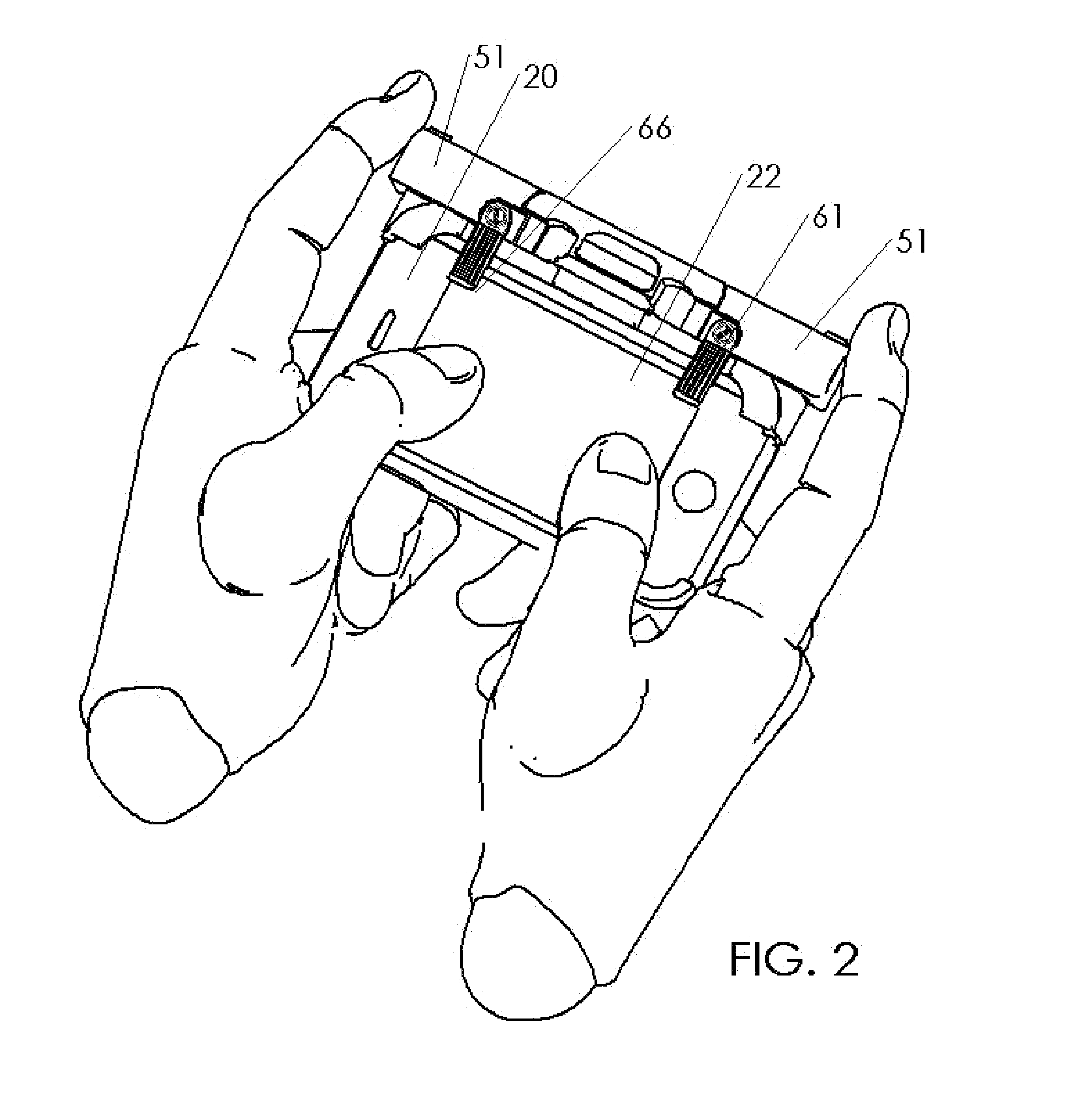
The present invention is a touch screen interface attachment for mobile devices that offers multiple inputs through mechanical and electrical devices attached to a touch screen. This invention aims to overcome the limitations of touch screen interfaces by simulating the play action of console game controllers on a touch screen device. Additionally, the invention can be incorporated into a mobile device case or screen protector, providing off-screen tactile inputs to the touch screen. The invention also provides an improved method for texting through the use of touch pads and external buttons on the phone.

Problems solved by technology

The current input limitations of touch screens greatly impair game play and have largely prevented the migration of most popular console and PC games to smart phones.

Method used


Image

  • Multi-touch input device
  • Multi-touch input device
  • Multi-touch input device

Examples


third embodiment

[0060]With reference to FIG. 5, the invention described utilizes a mechanical assembly combined with the capacitive link that is compactly integrated into a pistol shaped assembly 80. The assembly is comprised of a handle 81 designed for the user to grasp modeled after a gun, gaming controller, joystick or other, a trigger 82 as a user input which is protected by a trigger guard 83, that is mounted to a frame 84 that reacts against a clamp 85 to hold a tablet PC or iPad™ type device 25. The assembly 80 can easily be reconfigured to clamp the tablet 25 on the on the bottom with the handles 81 in a vertical position or on the side with the handles in a horizontal position. A moveable stylus 86 touches the screen 22 and is electrically coupled to a contact that closes when the user pulls the trigger thereby coupling the user's capacitance to the stylus. A variation of this embodiment could include a multi-touch input 87 such as a touch pad, hat switch, thumb stick or other input couple...

first embodiment

[0065]Referring to FIGS. 9-11, an easily attachable mobile tablet handle embodiment of the invention is described. The first embodiment described is comprised of two multi-touch input device handle assemblies 210 that readily attach to either side of a mobile device 209. Each handle roughly approximates one half of a typical console game controller. The handle assemblies are installed on a mobile tablet or smart phone by a means that is readily attachable and detachable such as a clamp. When installed on the device a portion of the handle 210 overlays the touch screen 206 and communicates with the touch screen using a capacitive link or circuit. The user operates controls 219 on the handles similar to those found in standard console style gamepads. The invention's controls operate switches that connect the user's capacitance, the capacitance of the device's frame or a standalone capacitor to capacitive pads positioned on the touch screen thereby selectively transferring electrical c...


PUM


Abstract

An interface is provided for a device having a touch screen such as a smart phone or tablet computer that extends the touch screen input to areas outside the touch screen area. The interface has a housing which attaches to the device. One or more input controls are mounted on the housing. The controls can be joysticks, buttons, touch pads, levers, triggers, keyboards, etc. Conductive pads are connected to the housing and and capacitively interact with the touch screen. The interface contains circuitry that transmits an electrical or capacitive signal from the user's manipulation of the controls to the conductive pads in order to activate selected areas of the touch screen. The housing may be made in multiple pieces to connect to different sides of the touch screen device.

Description

FIELD OF THE INVENTION[0001]The invention relates generally to the field of portable electronic devices with a touch screen, such as mobile phones, smart phones, tablet PCs and PDAs. More specifically, the present invention relates to the field of interaction with these devices through a remote input that activates a touch screen input.BACKGROUND OF THE INVENTION[0002]Touch screens are becoming the predominant way humans interact with mobile phones, smart phones, tablet PCs and PDAs. While touch screens have improved the user interface with customizable and flexible input screens which utilize tapping, swiping and multi-touch gestures, touch screens still largely continue to limit users holding a phone in a portrait orientation to a single input i.e. their forefinger or when the phone is held in a landscape orientation a dual input i.e. their left and right thumbs. This makes controlling programs designed to operate on console gaming units and PCs difficult.[0003]A further limitatio...

Claims


Application Information

Patent Timeline
Patent Type & Authority Applications(United States)
IPC IPC(8): G06F3/044G06F3/02G06F3/033
CPCG06F3/044G06F3/033G06F3/0213G06F1/1632G06F1/1671A63F13/98A63F13/837A63F13/245A63F13/2145A63F13/92G06F2203/04809G06F3/0443A63F13/24A63F13/26
Inventor MAUS, DARYL D.
Owner MAUS DARYL D
Learn More