
Light control method and lighting device using the same

a technology of lighting device and remote control, which is applied in the direction of lighting apparatus, light sources, instruments, etc., can solve the problems of confusing different buttons on the remote control, low accuracy of the arrangement, and high cost of the remote control and the accompanying receiver

Active Publication Date: 2013-05-16
OSRAM SYLVANIA INC
View PDF8 Cites 78 Cited by
  • Summary
  • Abstract
  • Description
  • Claims
  • Application Information

AI Technical Summary

Benefits of technology

The patent describes a technology that allows users to control a lighting device with gestures, even when the user is facing away from the sensor. The technology recognizes gestures in three-dimensional space, so the user is not limited to facing the sensor. This makes it easier for users to control the lighting device without having to look directly at it. The technology can be used to control the lighting device from a great distance or a wide angle.

Problems solved by technology

However, a user still needs to find and pick up the remote controller before he or she can control the device.
Further, the different buttons on a remote control can be confusing to the user.
Finally, the costs of a remote control and the accompanying receiver can be relatively high.
Such an arrangement is however relatively inaccurate, as the intensity of the reflected infrared signal heavily depends on the kind of object that is moved in the beam.
Other disadvantages include that the hand position can only control one attribute of the light, i.e. the brightness, and that complicated gestures cannot be differentiated and recognized.
Other disadvantages may include the inability to accurately select and control multiple light units.

Method used


Image

  • Light control method and lighting device using the same
  • Light control method and lighting device using the same
  • Light control method and lighting device using the same

Examples


Embodiment Construction

[0015]For a better understanding of the present invention, together with other and further objects, advantages and capabilities thereof, reference is made to the following disclosure and appended claims taken in conjunction with the above-described drawings.

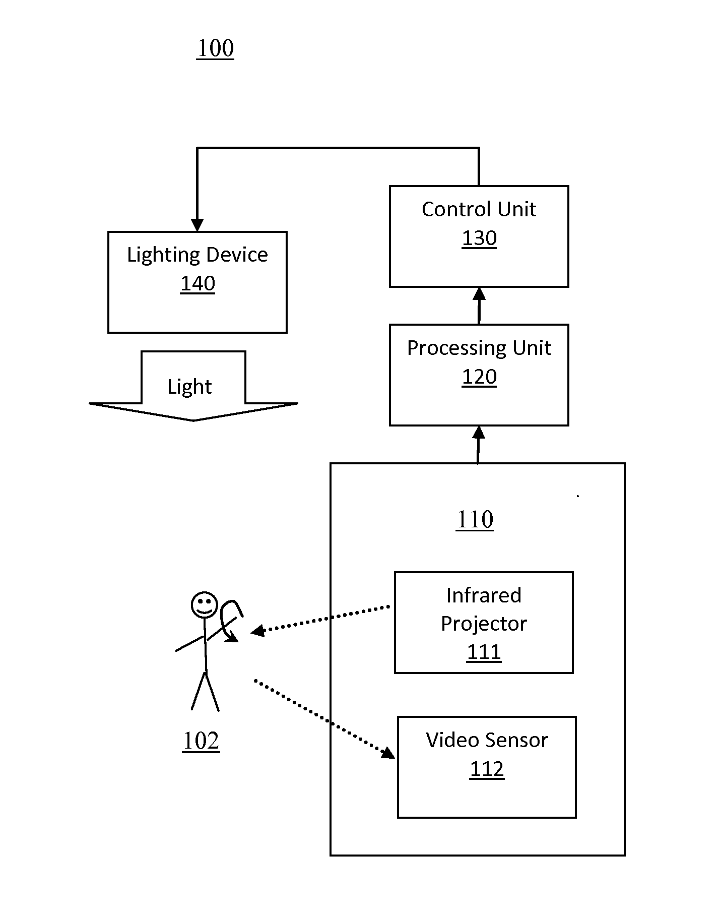
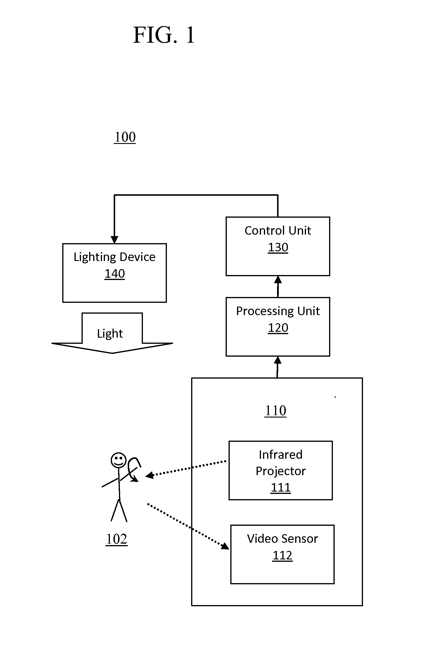
[0016]With reference to FIG. 1, a lighting device 100, in accordance with an embodiment of the invention is shown. The lighting device 100 is controllable by a motion of a user 102 in lighting environment. For instance, the lighting device 100 may be controllable by a hand gesture from the user in a living room environment. The lighting device includes a gesture mapping sensor 110, a processing unit 120, a controlling unit 130, and at least one light-emitting unit 140. The light-emitting unit 140 emits an output light and may include, but is not limited to, a light emitting diode (LED) for emitting an output light.

[0017]The gesture mapping sensor 110 may include an infrared projector 111 and a video sensor 112. The infrared proje...


PUM


Abstract

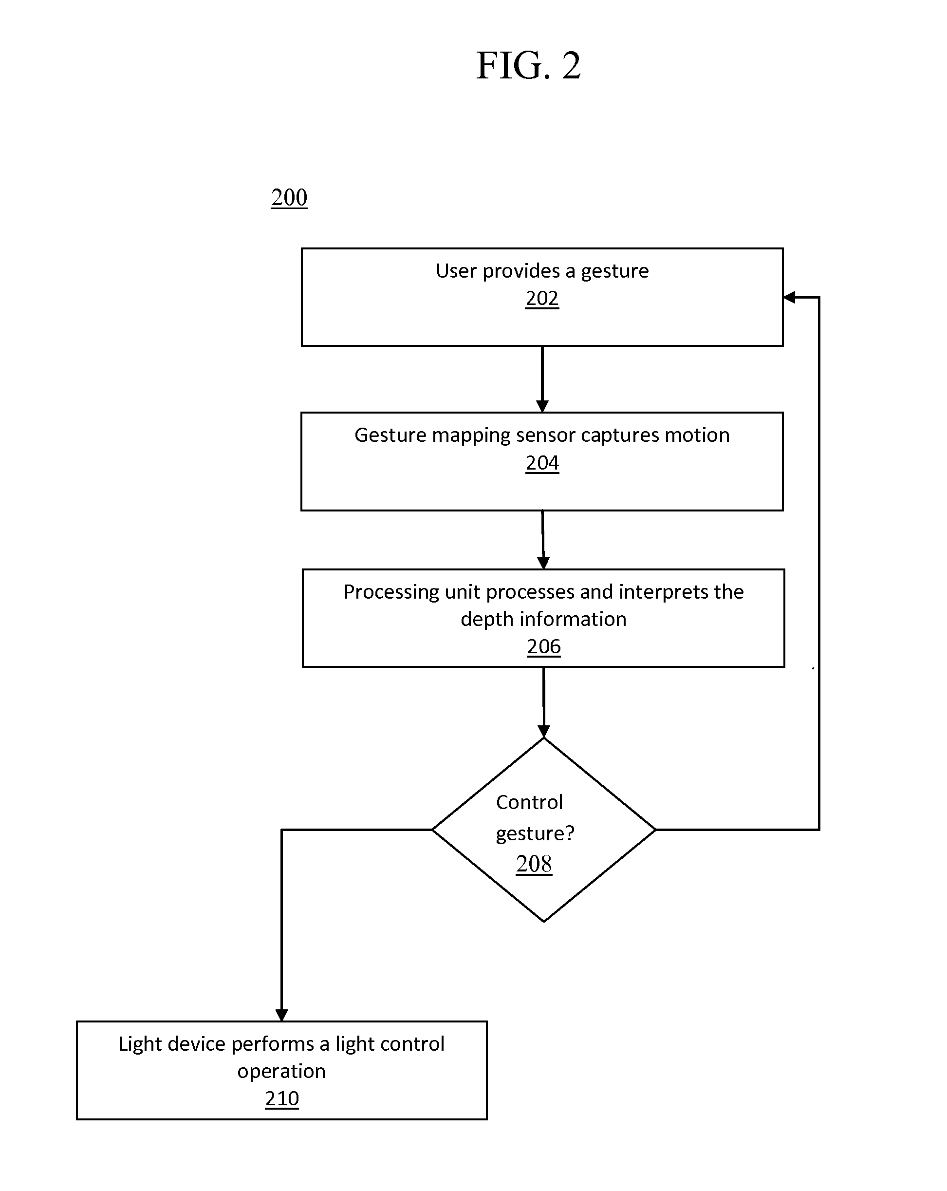
There is herein described a light output control method for a controlling a lighting device by a motion of an object near an environment, the lighting device comprising a video sensor and a light-emitting unit, the light output control method comprising steps of emitting an infrared light onto at least a part of the object and at least a part of the environment, collecting the infrared light reflected by at least the part of the object and at least the part the environment as a two-dimensional depth data sequence of the video sensor, computing the motion of the object by utilizing the two-dimensional depth data sequence, and controlling the light-emitting unit to change an attribute of the output light if the motion of the object complies with a predetermined condition.

Description

TECHNICAL FIELD[0001]This invention relates to controlling lighting devices using gesture recognitions.BACKGROUND[0002]Remote controllers are important components of many electrical devices such as TVs, DVD players, air conditioners, home theater systems. Nowadays, remote controllers are also used to control the lighting of the house. The use of remote controllers facilitates the controlling process since the user can control the device remotely. However, a user still needs to find and pick up the remote controller before he or she can control the device. In addition, many different remote controls are already present in the room for multiple electronic devices. Further, the different buttons on a remote control can be confusing to the user. Finally, the costs of a remote control and the accompanying receiver can be relatively high.[0003]It is desirable to reduce the dependence on remote controller while still providing simple and easy control devices. For example, lighting systems ...

Claims


Application Information

Patent Timeline
Patent Type & Authority Applications(United States)
IPC IPC(8): G09G5/00
CPCH05B37/0227H05B47/125Y02B20/40
Inventor SPAULDING, JEREMYHOLT, JEFFREYJESSEN, KARLIN
Owner OSRAM SYLVANIA INC
Learn More