
Exhaust gas diffuser for a gas turbine and a method for operating a gas turbine that comprises such an exhaust gas diffuser

a technology of exhaust gas diffuser and gas turbine, which is applied in the direction of machines/engines, stators, liquid fuel engines, etc., can solve the problems of inability to prevent backflow, and inability to influence the flow in the center of the exhaust gas diffuser, so as to achieve the effect of reducing the demands on the drive and effectively avoiding the flow of near-wall leakag

Inactive Publication Date: 2013-05-09
SIEMENS AG
View PDF2 Cites 4 Cited by
  • Summary
  • Abstract
  • Description
  • Claims
  • Application Information

AI Technical Summary

Benefits of technology

The invention is a space-saving exhaust gas diffuser for a gas turbine that aims to achieve highest efficiency and prevent flow separations and backflow zones. It also ensures reliable operation of downstream boilers and afterburners for each operating state of the gas turbine. Additionally, a method for operating a gas turbine with the exhaust gas diffuser is also disclosed.

Problems solved by technology

The fact that the guiding body is comparatively long and on account of its length therefore has to be supported by means of additional struts is disadvantageous, however.
They have particularly large backflow zones, however.
Nevertheless, the short gas turbine hubs are also particularly cost effective.
Influencing of the flow in the center of the exhaust gas diffuser, where backflows can occur, is not possible, however, with the aid of the guiding element.
In the case of backflow zones reaching too far downstream, there is the risk that these can reach a boiler arranged downstream of the exhaust gas diffuser, which significantly degrades its principle of operation.
Also, in the case of afterburners which are installed there, these would lead to a flashback, as a result of which the combined operation of gas turbines and afterburners is severely limited.

Method used


Image

  • Exhaust gas diffuser for a gas turbine and a method for operating a gas turbine that comprises such an exhaust gas diffuser
  • Exhaust gas diffuser for a gas turbine and a method for operating a gas turbine that comprises such an exhaust gas diffuser
  • Exhaust gas diffuser for a gas turbine and a method for operating a gas turbine that comprises such an exhaust gas diffuser

Examples


Embodiment Construction

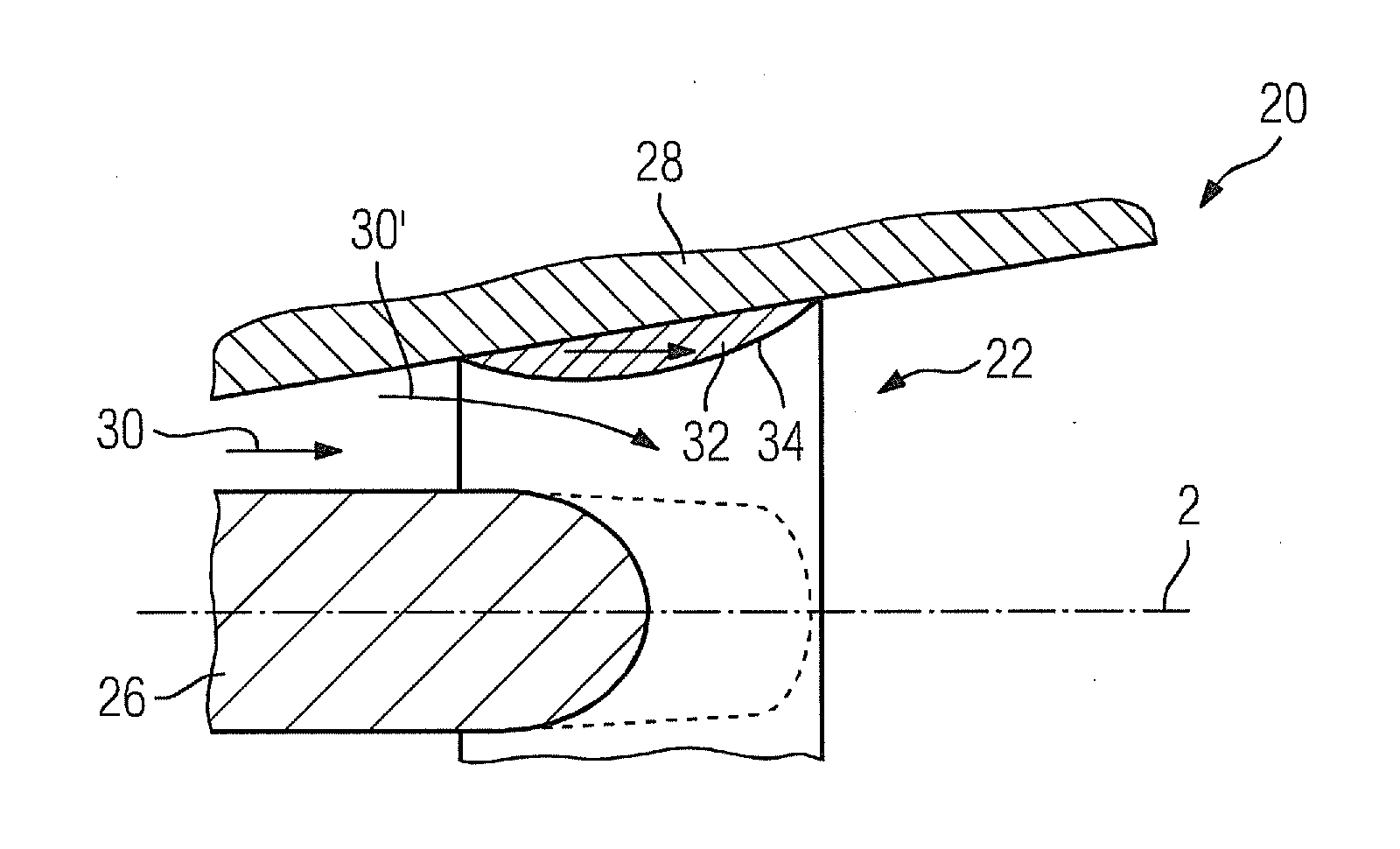
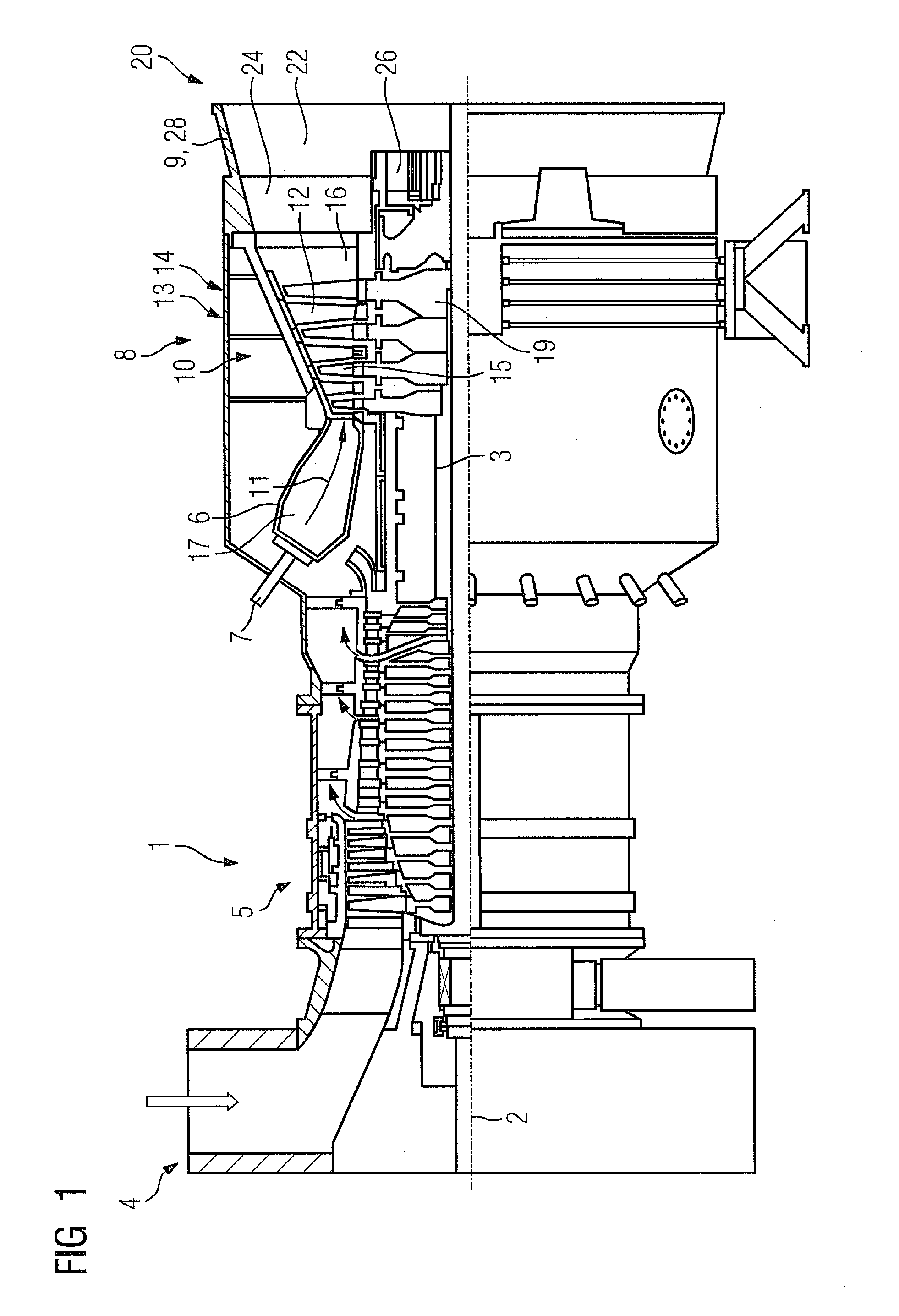
[0025]FIG. 1 shows a gas turbine 1 in a longitudinal partial section. Inside, it has a rotor 3—also referred to as a turbine rotor assembly—which is rotatably mounted around a machine axis 2. An intake housing 4, a compressor 5, a toroidal annular combustion chamber 6 with a plurality of burners 7 arranged rotationally symmetrically to each other, a turbine unit 8 and an exhaust housing 9 are arranged in series along the rotor 3. The annular combustion chamber 6 encloses a combustion space 17 which is connected to an annular hot gas passage 16. Four series-connected blade stages 10 form the turbine unit 8 there. Each blade stage 10 is formed from two blade rings. A row 14 formed from rotor blades 15 follows in each case a stator blade row 13 in the hot gas passage 16, as seen in the flow direction of a hot gas 11 which is produced in the annular combustion chamber 6. The stator blades 12 are fastened on the stator, whereas the rotor blades 15 of a row 14 are attached in each case on...


PUM


Abstract

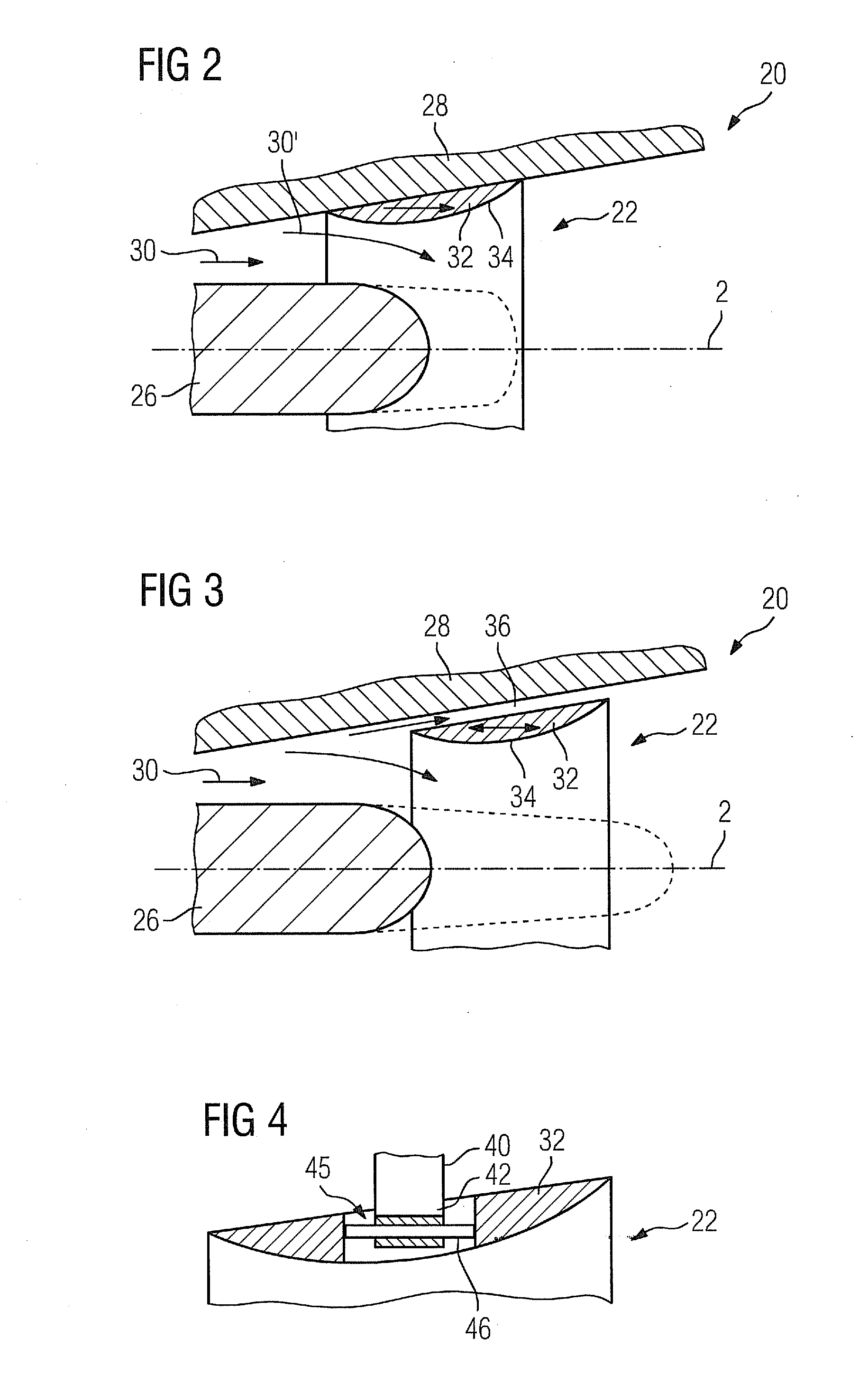
An exhaust gas diffuser for a gas turbine is provided. The diffuser has an annular outer wall for guiding the diffuser flow and in which an annular guiding element is arranged concentrically to the outer wall and influences the diffuser flow. The guiding element has a surface which is radially directed inwards and has a circumferential contour that is convex in the longitudinal section to form a displacement element. The guiding element is axially displaceable between two positions so that the guiding element, when in a first position, allows a flow between the guiding element and outer wall and, when in a second position, largely prohibits a flow between the guiding element and outer wall. The aerodynamic effect of the diffuser is improved and simultaneously optimal adapted for a plurality of operational gas turbine states.

Description

CROSS REFERENCE TO RELATED APPLICATIONS[0001]This application is the U.S. National Stage of International Application No. PCT / EP2011 / 061944 filed Jul. 13, 2011 and claims the benefit thereof. The International Application claims the benefits of European application No. 10007333.7 filed Jul. 15, 2010, both of the applications are incorporated by reference herein in their entirety.FIELD OF THE INVENTION[0002]The invention relates to an exhaust gas diffuser for a gas turbine, having an annular outer wall for guiding the diffuser flow, in which an annular guiding element, which is arranged concentrically to the outer wall, is provided for influencing the diffuser flow. In addition, the invention relates to a method for operating a gas turbine having an exhaust gas diffuser of the aforesaid type.BACKGROUND OF THE INVENTION[0003]Gas turbines and the exhaust gas diffusers used for these have been known at the latest from the prior art. For example, an exhaust gas diffuser with a comparativ...

Claims


Application Information

Patent Timeline
Patent Type & Authority Applications(United States)
IPC IPC(8): F04D29/54
CPCF01D9/02F01D17/141F05D2250/324F04D29/54F05D2250/711F01D25/30
Inventor BROKER, MARCBUCHAL, TOBIAS
Owner SIEMENS AG
Learn More