
Network virtualization apparatus and method with scheduling capabilities

a network virtualization and scheduling technology, applied in electrical appliances, digital transmission, data switching networks, etc., can solve the problems of increasing processing difficulty, l2 domains cannot l2 domains are unable to scale to large sizes, so as to reduce the overall network convergence time

Active Publication Date: 2013-05-09
NICIRA
View PDF2 Cites 77 Cited by
  • Summary
  • Abstract
  • Description
  • Claims
  • Application Information

AI Technical Summary

Benefits of technology

This patent describes a control system that optimizes different parts of the system to reduce the time it takes for the network to converge. When there are a lot of changes to different parts of the system, the controller responsible for managing them groups the changes based on which parts of the system they affect. This reduces the time it takes to update each part of the system because all resources are dedicated to updating a single part at a time. Additionally, when data is propagated to the switching elements or other controllers, the controller's network operating system aggregates the data before sending it out. This helps the switching elements or other controllers process the data quickly and efficiently, further reducing the time it takes for the network to converge.

Problems solved by technology

This process is of increased difficulty where the network switching elements are shared across multiple users.
Many approaches taken to address one of these goals results in hampering at least one of the others.
For instance, one can easily provide network mobility for virtual machines within a layer 2 (L2) domain, but L2 domains cannot scale to large sizes.
Furthermore, retaining user isolation greatly complicates mobility.

Method used


Image

  • Network virtualization apparatus and method with scheduling capabilities
  • Network virtualization apparatus and method with scheduling capabilities
  • Network virtualization apparatus and method with scheduling capabilities

Examples


Embodiment Construction

[0048]In the following detailed description of the invention, numerous details, examples, and embodiments of the invention are set forth and described. However, it will be clear and apparent to one skilled in the art that the invention is not limited to the embodiments set forth and that the invention may be practiced without some of the specific details and examples discussed.

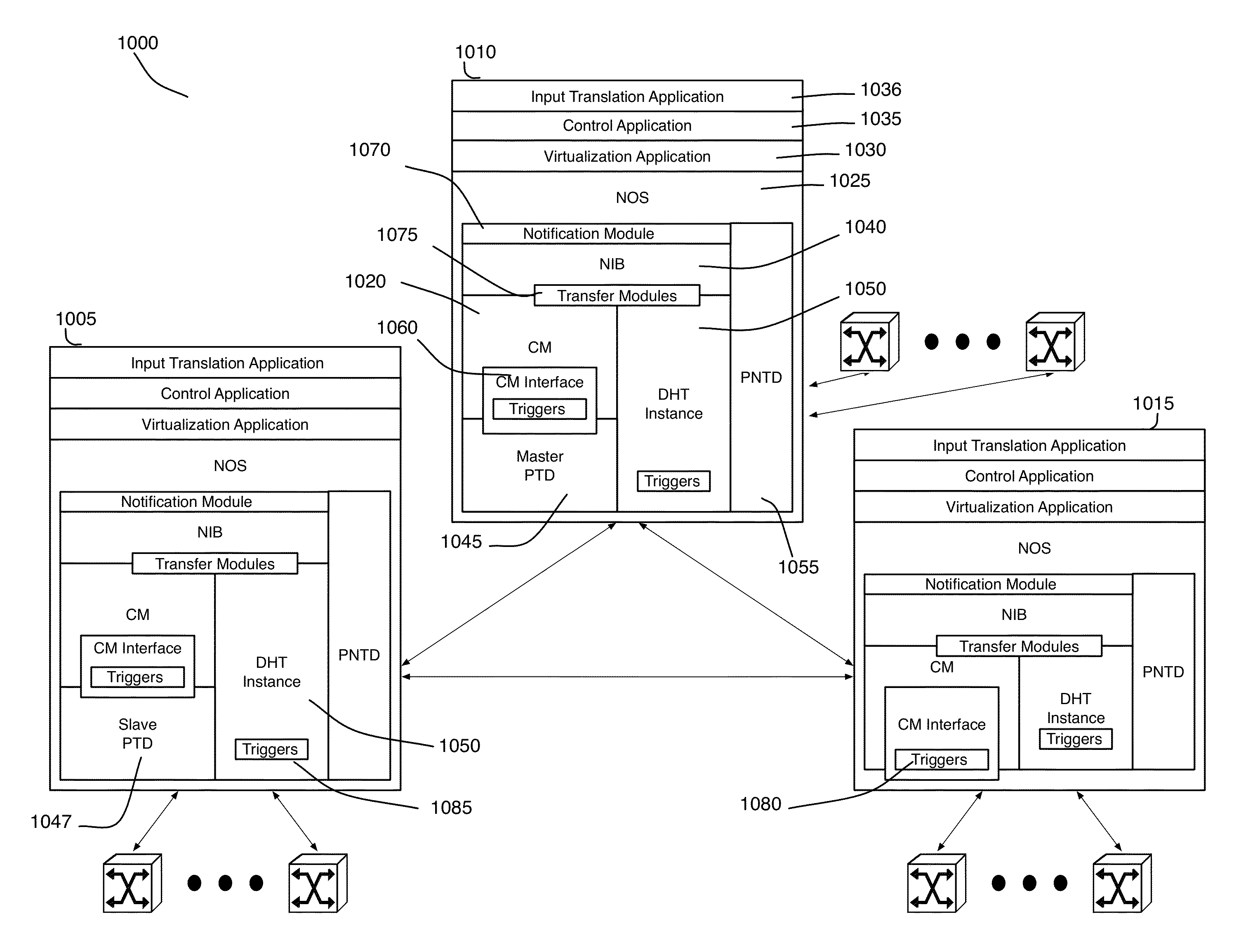
[0049]Some of the embodiments described below are implemented in a novel network control system that is formed by one or more controllers (controller instances) for managing several managed switching elements. In some embodiments, the control application of a controller receives logical control plane (LCP) data and converts this data to logical forwarding plane (LFP) data that is then supplied to the virtualization application. The virtualization application then generates the physical control plane data from the LFP data. The physical control plane data is propagated to the managed switching elements.

[0050]In...


PUM


Abstract

Some embodiments provide a controller for managing several managed switching elements that forward data in a network. The controller includes an interface for receiving input logical control plane data in terms of input events data. The controller includes an input scheduler for (1) categorizing the input events data into different groups based on certain criteria and (2) scheduling supplying of the input event data into a converter based on the groups so that the converter processes a group of input events data together. The controller includes the converter for converting the input logical control plane data to output logical forwarding plane data. The controller includes a network information base (NIB) data structure module for storing the output logical forwarding plane data. The logical forwarding plane data is for subsequent translation into physical control plane data.

Description

CLAIM OF BENEFIT TO PRIOR APPLICATIONS[0001]This application is a continuation-in-part application of U.S. patent application Ser. No. 13 / 589,077, filed on Aug. 17, 2012; and U.S. patent application Ser. No. 13 / 589,078, filed on Aug. 17, 2012. U.S. patent application Ser. No. 13 / 589,077 and U.S. patent application Ser. No. 13 / 589,078 claim the benefit of U.S. Provisional Application 61 / 551,425, filed Oct. 25, 2011; U.S. Provisional Application 61 / 551,427, filed Oct. 25, 2011; U.S. Provisional Application 61 / 577,085, filed Dec. 18, 2011; U.S. Provisional Application 61 / 595,027, filed Feb. 4, 2012; U.S. Provisional Application 61 / 599,941, filed Feb. 17, 2012; U.S. Provisional Application 61 / 610,135, filed Mar. 13, 2012; U.S. Provisional Application 61 / 635,056, filed Apr. 18, 2012; U.S. Provisional Application 61 / 635,226, filed Apr. 18, 2012; and U.S. Provisional Application 61 / 647,516, filed May 16, 2012. This application claims the benefit of U.S. Provisional Application 61 / 551,425, ...

Claims


Application Information

Patent Timeline
Patent Type & Authority Applications(United States)
IPC IPC(8): H04L12/26H04L12/28
CPCH04L41/0893H04L41/0663H04L41/0889H04L41/0813H04L41/40
Inventor KOPONEN, TEEMUTHAKKAR, PANKAJ
Owner NICIRA
Learn More