
Method and system for imaging device characterization including look-up table construction via tensor decomposition

a technology of imaging device and look-up table, applied in the field of color characterization, can solve the problems of color drift on the printer, and high cost of color accuracy

Inactive Publication Date: 2013-05-09
XEROX CORP
View PDF3 Cites 5 Cited by
  • Summary
  • Abstract
  • Description
  • Claims
  • Application Information

AI Technical Summary

Benefits of technology

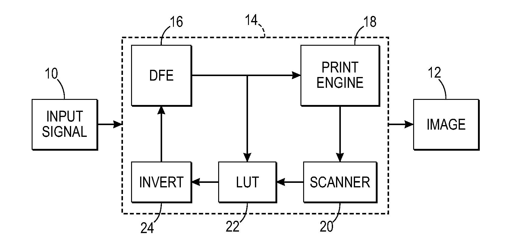
This patent describes a method and system for creating a multidimensional look-up-table (LUT) that characterizes a color device, such as a printer. The LUT maps device dependent color space values to device independent color space values. The method involves rendering a set of patches with the color device and measuring the associated colors to generate device independent color space values. Tensor terms are then calculated and used to generate the multidimensional LUT. The system includes a controller that uses the LUT to map device dependent color space values to device independent color space values. The technical effect of this patent is improved color accuracy and consistency in printing, as the LUT ensures that the correct colors are produced.

Problems solved by technology

Colors on a printer tend to drift over time due to ink / toner variations, temperature fluctuations, type of media used, environment, etc.
For color printers, characterization is an expensive process involving large numbers of patch measurements and subsequent computation to derive satisfactorily accurate color lookup-tables (LUTs).
Because the two dimensional LUTs are by construction smaller than three or four dimensional LUTs, for example, a patch reduction is obtained, but at the cost of color accuracy.
The PCA method may drastically reduce the patches required during calibration, but its characterization process is relatively complicated and required a relatively large number of printed patches proportional to the number of nodes in the multi-dimensional LUT times the number of different possible printer states due to changes in paper, environmental conditions, aging, etc.
From a mathematical viewpoint, tensor decompositions naturally unearth structure in multi-dimensional LUTs which is otherwise hard to predict.

Method used


Image

  • Method and system for imaging device characterization including look-up table construction via tensor decomposition
  • Method and system for imaging device characterization including look-up table construction via tensor decomposition
  • Method and system for imaging device characterization including look-up table construction via tensor decomposition

Examples


Embodiment Construction

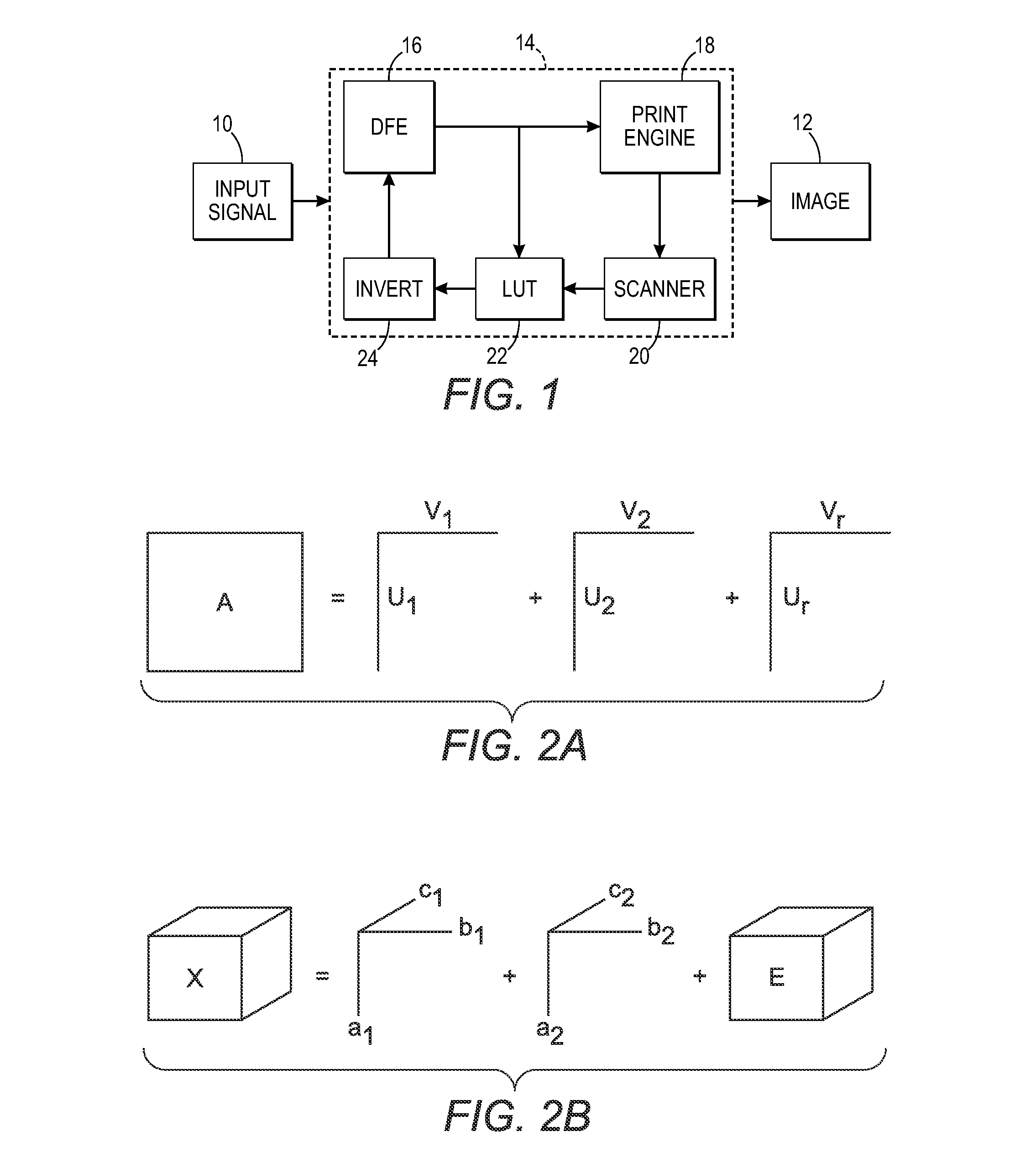
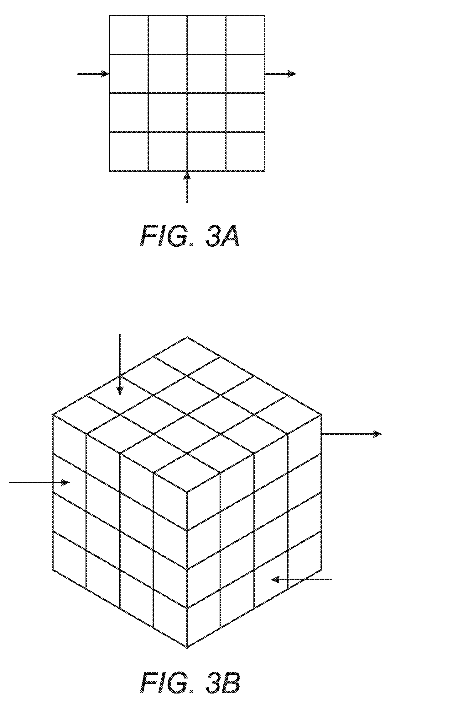
[0033]The subject embodiments relate to representing look-up tables for characterizing a color device such as a printer or other imaging devices, as tensors, and then employing tensor decompositions such as parallel factor analysis methods to obtain compact representations of the LUTs. Tensors are N-way arrays or higher-dimensional generalization of matrices. Employing tensor decompositions is analogous to prior known matrix decomposition techniques having a similar objective of compacting LUT representations.

[0034]More particularly, the subject embodiments comprise first, adapting tensors to represent an n-dimensional lattice to a real number map which typically comprises a multi-dimensional color look-up table, and second, using parallel factor analysis on the LUT tensors to unearth structure in the LUTs leading to methods that can derive the LUT with reduced effort, i.e., reduce storage, computation and / or measurements in the printing device processor means.

[0035]According to thi...


PUM


Abstract

A method and apparatus for characterizing the performance of a printing device comprising printing a target set of patches with the device and measuring the printing device response with the printed target set; compiling a LUT from the printed target set and measured response; and representing the LUT as a tensor. According to one exemplary embodiment, tensor decomposition / parallel factor analysis is employed for compacting the tensor representation of the LUT.

Description

[0001]This application claims priority to U.S. Provisional Patent Application No. 61 / 556,352 by Maltz et al., filed Nov. 7, 2011, entitled “IMAGING DEVICE COLOR CHARACTERIZATION INCLUDING COLOR LOOK-UP TABLE CONSTRUCTION VIA TENSOR DECOMPOSITION” and is incorporated herein by reference in its entirety.CROSS REFERENCE TO RELATED PATENTS AND APPLICATIONS[0002]U.S. Patent Application Publication No. 2010 / 0183220 by Monga et al., published Jul. 22, 2010 and entitled “IMAGING DEVICE COLOR CHARACTERIZATION INCLUDING COLOR LOOK-UP TABLE CONSTRUCTION VIA TENSOR DECOMPOSITION” is incorporated herein by reference it its entirety.BACKGROUND[0003]The presently disclosed embodiments are directed to color printing and display systems; and especially color characterization of such systems.[0004]In today's business and scientific world, color has become essential as a component of communication. Color facilitates the sharing of knowledge and ideas. For example, companies involved in the development...

Claims


Application Information

Patent Timeline
IPC IPC(8): H04N1/60G09G5/02G06K9/00
CPCG09G5/06G09G2320/0276H04N1/60G06K9/00H04N1/6033
Inventor MALTZ, MARTIN S.FAN, ZHIGANG
Owner XEROX CORP
Learn More