
Articulated seating system

a seating system and articulation technology, applied in the direction of movable seats, vehicle components, vehicle arrangements, etc., can solve the problems of limited use, limited operation and construction of the mechanism used to raise and lower the vertical position of the seat of such seating systems, and limited use of the seating system

Active Publication Date: 2013-05-09
BRAUNABILITY EURO AB
View PDF7 Cites 19 Cited by
  • Summary
  • Abstract
  • Description
  • Claims
  • Application Information

AI Technical Summary

Benefits of technology

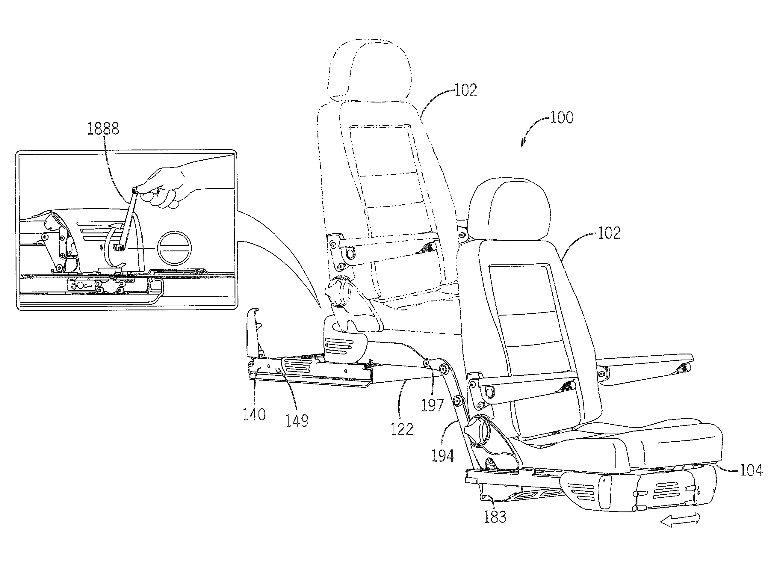
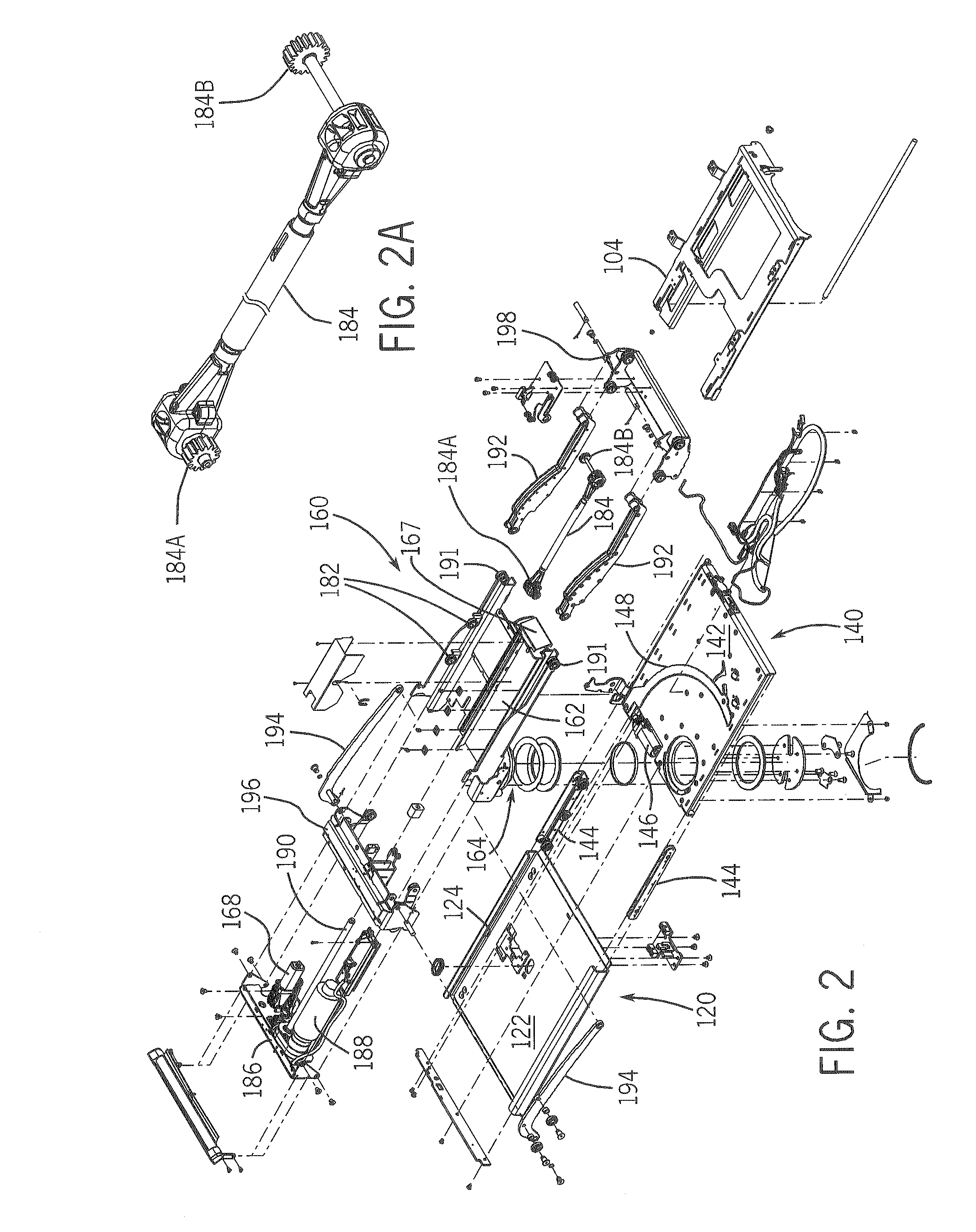
The present invention is an articulated seating system for motor vehicles that allows for easy access for users with limited mobility or strength. The system includes a mounting assembly, fore-aft slide assembly, swivel assembly, and extension assembly, which are all driven by a motor or other power source. The user seat can be extended from its secured position in the motor vehicle to an access position outside the vehicle, making it easier for users to enter and exit. The system uses extension guide rollers and support arms that create a different leverage arrangement, allowing for easy adjustments during the extended and retracted positions of the seat. This system can be used in motor vehicles with limited transit corridors and can even be powered by a manual operation system in case of power loss or failure. The technical effects of this invention include improved accessibility for users and a more convenient and comfortable seating system for motor vehicles with disabled or elderly users.

Problems solved by technology

Previous seating systems have been limited in several ways.
This space requirement for installation of such systems has thus limited their use to only large vehicles that have sufficient clearance to permit such operation on the driver's side of the interior cabin or compartment.
Finally, the mechanisms used to raise and lower the vertical position of the seat of such seating systems have been limited in their operation and construction.

Method used


Image

  • Articulated seating system
  • Articulated seating system
  • Articulated seating system

Examples


Embodiment Construction

[0027]The following detailed description of the invention, including the Figures, will refer to one or more invention embodiments, but is not limited to such embodiments. Rather, the detailed description is intended only to be illustrative. Those skilled in the art will readily appreciate that the detailed description given with respect to the Figures is provided for explanatory purposes as the invention extends beyond such specific embodiments. Embodiments of the invention provide apparatus, systems, methods, techniques, etc. including and pertaining to (but not limited to) articulated seating systems for and / or in motor vehicles and the like, including articulated seating systems that are suited for motor vehicles having a spacing (referred to as a “transition corridor”) between the steering wheel and nearest B-pillar of 18 to 22 inches. Other structures and uses will be apparent to those skilled in the art after considering the following disclosure and the Figures provided herewi...


PUM


Abstract

An articulated seating system supports a user seat using a mounting assembly, a fore-aft slide assembly, a swivel assembly and an extension assembly driven by a drive packet having one or more motors or the like. The seat is moved from a secured drive position (e.g., a standard interior vehicle seat position) to an extension position (wherein the seat faces out of a vehicle doorway) and finally to an access position outside the vehicle, facilitating access for a user having limited mobility, strength, etc. Extendible supporting arms engage and enclose guide rollers to allow stable and precise control of lateral and vertical seat movement. Moving between the drive and extension positions, the seat can move through a narrow transition corridor in the motor vehicle. The motors can operate manually to allow securing the seat in the drive position despite power or other failure.

Description

PRIORITY CLAIM AND CROSS-REFERENCE TO RELATED APPLICATIONS[0001]This application claims priority to and the benefit of the following prior filed copending application:[0002]U.S. Ser. No. 61 / 556,214 (Atty. Docket No. 0201-p25p1) filed Nov. 5, 2011, entitled ARTICULATED SEATING SYSTEM. The entire disclosure of that application (including any appendices) is incorporated herein by reference in its entirety for all purposes.STATEMENT REGARDING FEDERALLY SPONSORED RESEARCH OR DEVELOPMENT[0003]Not applicable.REFERENCE TO SEQUENCE LISTING, A TABLE, OR A COMPUTER PROGRAM LISTING COMPACT DISK APPENDIX[0004]Not applicable.BACKGROUND[0005]1. Technical Field[0006]This invention relates generally to apparatus, systems, methods, techniques, etc. for implementing seating systems that permit movement of a passenger or driver in a vehicle from an interior seat position (e.g., a driving position behind the motor vehicle steering wheel, or a passenger seat position) to an access position outside the mo...

Claims


Application Information

Patent Timeline
IPC IPC(8): B60N2/24B60N2/16B60N2/14
CPCB60N2/14B60N2/0232B60N2/1625B60N2002/0256B60N2002/0236B60N2002/024B60N2/245B60N2/0256B60N2/02258B60N2/02253B60N2/02246
Inventor SLUNGARE, HANS BERTILBERGSTRAND, JOAKIM LARS
Owner BRAUNABILITY EURO AB
Learn More