Tubular catcher system and method

a tubular catcher and system technology, applied in the field of well drilling and processing, can solve the problems of tubular dropping through the rig floor and down the well, and abandoning the well

Active Publication Date: 2013-05-09
NABORS DRILLING TECH USA INC
View PDF2 Cites 11 Cited by
  • Summary
  • Abstract
  • Description
  • Claims
  • Application Information

AI Technical Summary

Benefits of technology

[0006]The present invention is designed to respond to such a need. In accordance with one aspect of the invention, a drilling system comprises a sensor configured to detect the motion of a tubular, a gripping mechanism to stop the downward motion of a tubular dropping toward a wellbore, an actuation mechanism to close the gripping mechanism against the tubular, and a trigger mechanism to activate the actuation mechanism when the sensor recognizes that the tubular is dropping too quickly. The drilling system also includes a shock absorber to transfer energy from the falling tubular through a support structure and to the ground.

Problems solved by technology

Occasionally, the coordination between gripping of the tubular with the top drive (or with a casing drive system attached to the top drive) and release of the slips fails, resulting in the tubular dropping through the rig floor and down the well.
This type of event is usually costly and, in instances where the tubular cannot be salvaged, may result in abandoning the well.

Method used


Image

  • Tubular catcher system and method
  • Tubular catcher system and method
  • Tubular catcher system and method

Examples


Embodiment Construction

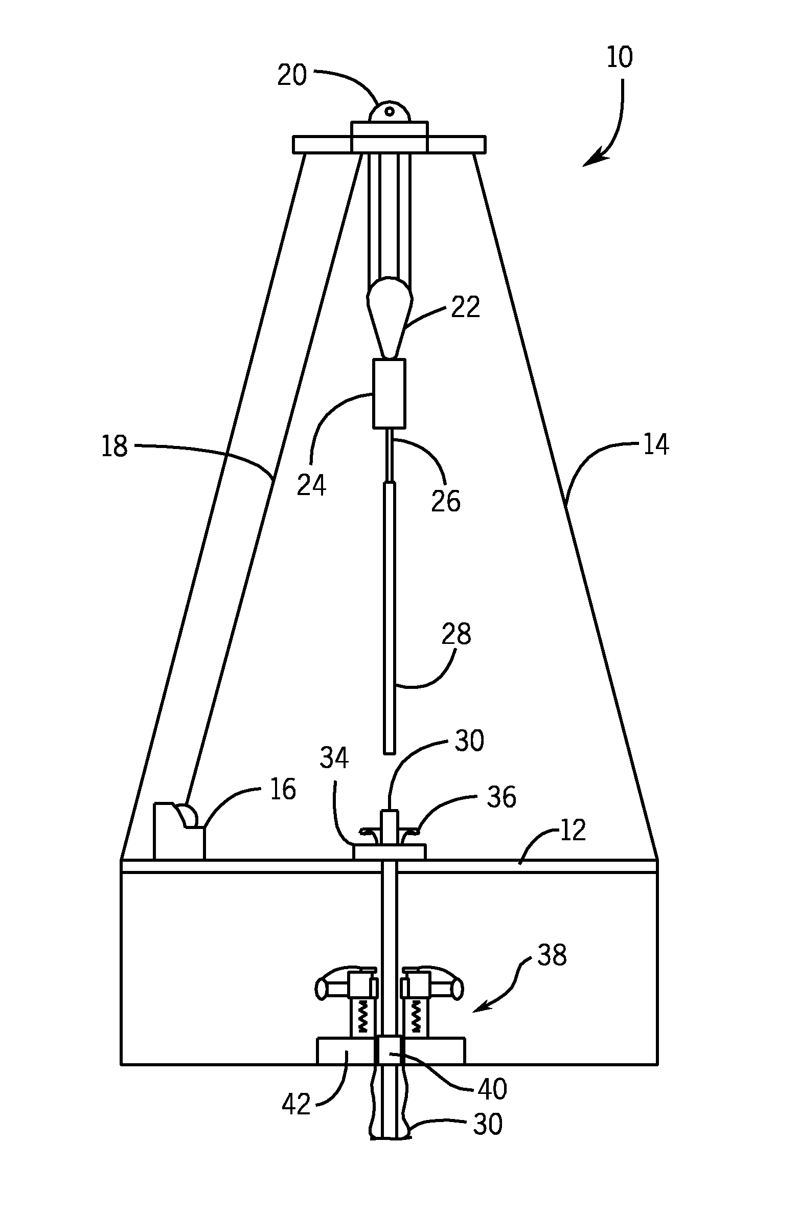
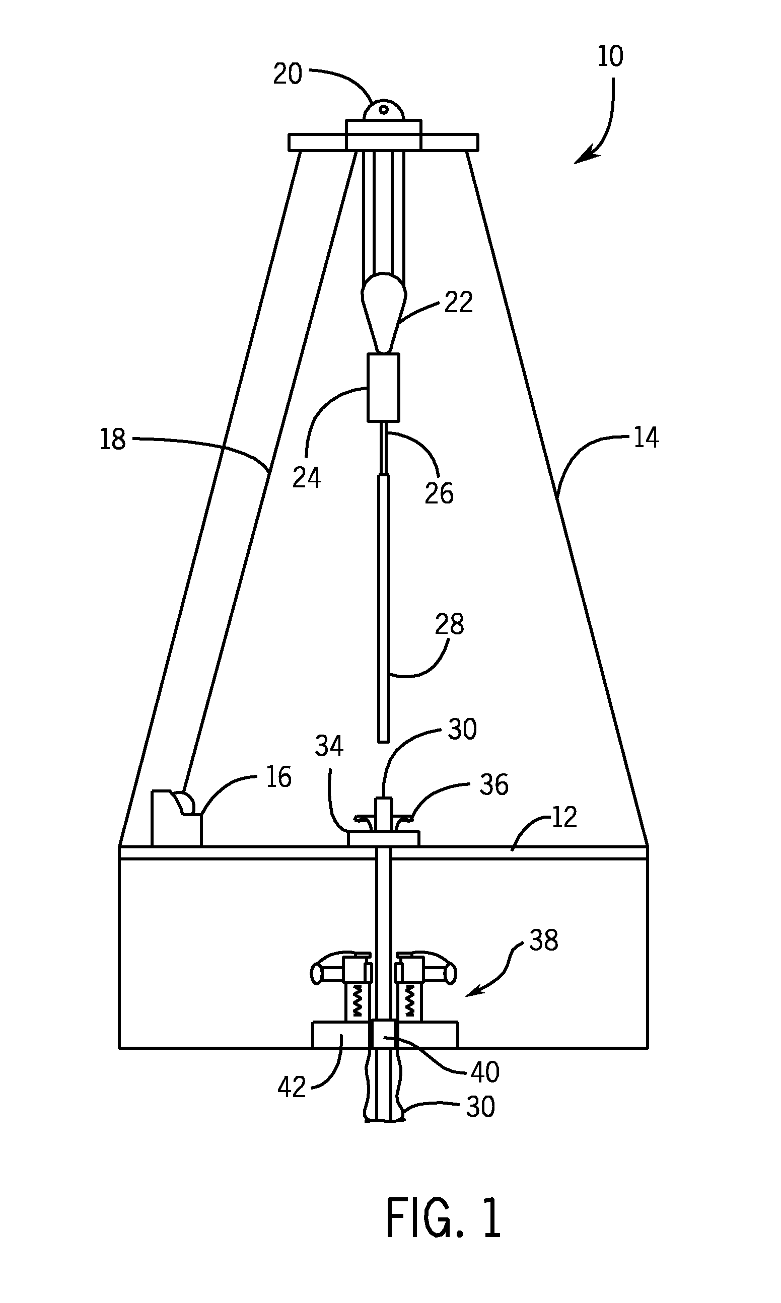
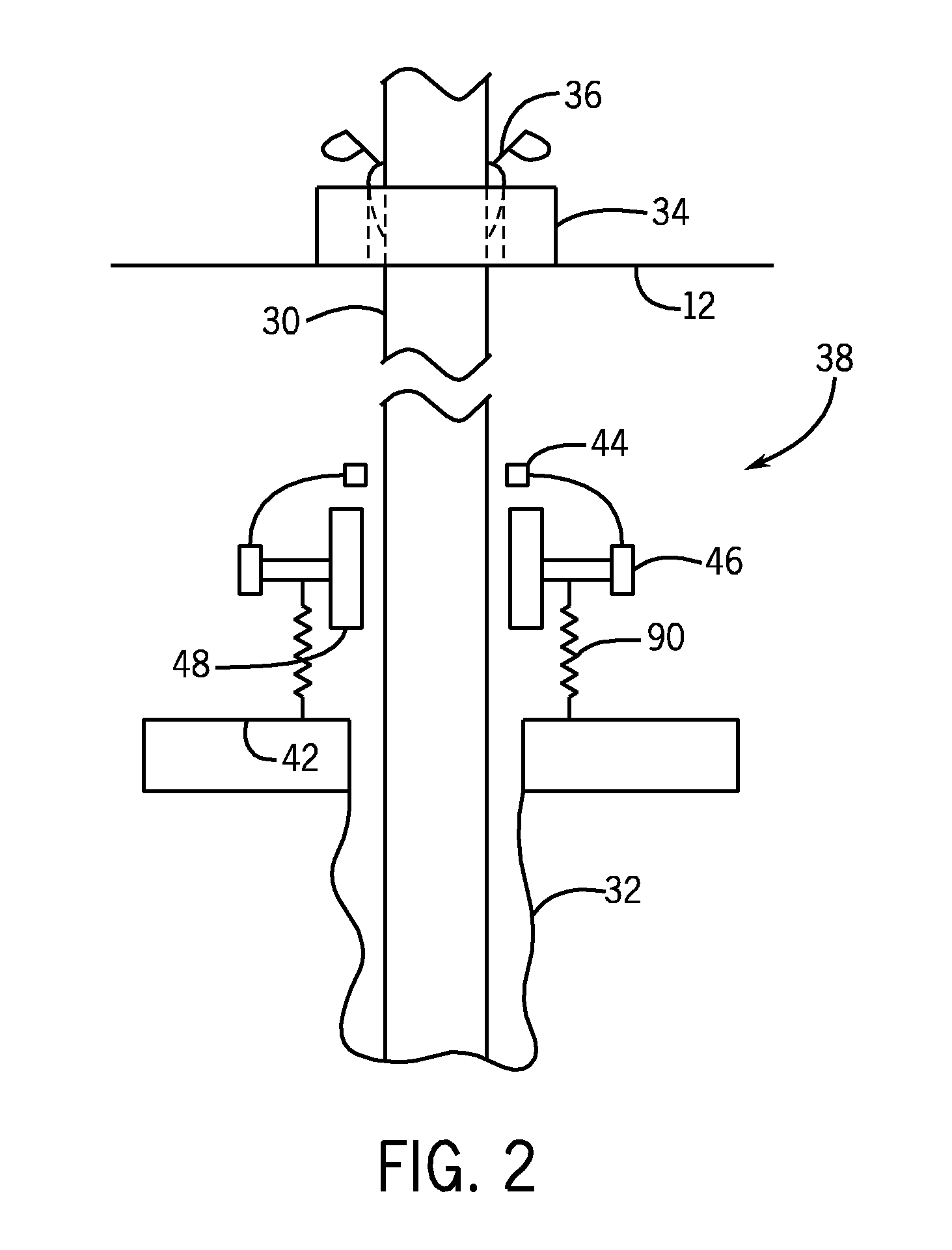
[0024]The present invention provides a novel tubular catcher system and method that can be used in casing and drilling operations. The presently disclosed techniques allow for a dropped tubular (e.g., string of casing or drill pipe) to be grasped before falling into a wellbore. In one embodiment, a sensor detects the velocity or acceleration of the tubular, and activates an actuation mechanism when the velocity or acceleration reaches a threshold (indicating a free-falling tubular). The actuation mechanism then forces a gripping mechanism to engage with the falling tubular in order to stop the downward motion, and a shock absorber dissipates the energy from the falling tubular.

[0025]Turning now to the drawings, FIG. 1 is a schematic representation of a drilling rig 10 in the process of drilling a well in accordance embodiments of the present techniques. The drilling rig 10 features an elevated rig floor 12 and a derrick 14 extending above the floor. A drawworks 16 supplies drilling ...


PUM


Abstract

Present embodiments are directed to a tubular catcher system configured to detect a falling tubular through a drilling rig and grip the tubular before it drops into the wellbore. A sensor configured to detect the velocity or acceleration of the tubular activates an actuation mechanism when the velocity or acceleration exceeds a specific threshold, indicating a falling tubular. The actuation mechanism forces a gripping mechanism into contact with the tubular, catching the tubular and sending energy from the tubular to a hydropneumatic shock absorber coupled to the actuation mechanism and/or the gripping mechanism.

Description

CROSS REFERENCE TO RELATED APPLICATIONS[0001]This application claims priority from and the benefit of U.S. Provisional Application Ser. No. 61 / 555,811, entitled “Tubular Catcher System and Method,” filed Nov. 4, 2011, which is hereby incorporated by reference for all purposes.BACKGROUND[0002]The invention relates generally to the field of drilling and processing of wells, and, more particularly, to a system and method for catching tubular that is dropped during a casing process, a drilling process, or another type of well processing operation.[0003]In conventional oil and gas operations, a well is typically drilled to a desired depth with a drill string, which includes drill pipe and a drilling bottom hole assembly. Once the desired depth is reached, the drill string is removed from the hole and casing is run into the vacant hole. Casing may be defined as pipe or tubular that is placed in a well to prevent the well from caving in, to contain fluids, and to assist with efficient extr...

Claims


Application Information

Patent Timeline
Patent Type & Authority Applications(United States)
IPC IPC(8): E21B47/09
CPCE21B44/00E21B23/01E21B19/165E21B41/0021E21B40/00
Inventor O'BLENES, JONATHAN BRIAN
Owner NABORS DRILLING TECH USA INC
Why Eureka
Try Eureka