Screwdriver

a screwdriver and screw technology, applied in the field of screwdrivers, can solve the problems of inconvenient process and bad transmission of large torque, and achieve the effect of reliable torque transmission apparatus and easy assembly

Inactive Publication Date: 2013-05-09
YIH CHENG FACTORY
View PDF6 Cites 5 Cited by
  • Summary
  • Abstract
  • Description
  • Claims
  • Application Information

AI Technical Summary

Benefits of technology

[0008]It is the primary objective of the present invention to provide a screwdriver with a reliable torque transmission apparatus that can easily be assembled.

Problems solved by technology

The process is however inconvenient.
However, the control strip 6 could easily snap and interfere with the insertion of the frame 21 in the cap 3, and this is bad for transmitting large torque.

Method used


Image

  • Screwdriver
  • Screwdriver
  • Screwdriver

Examples


Embodiment Construction

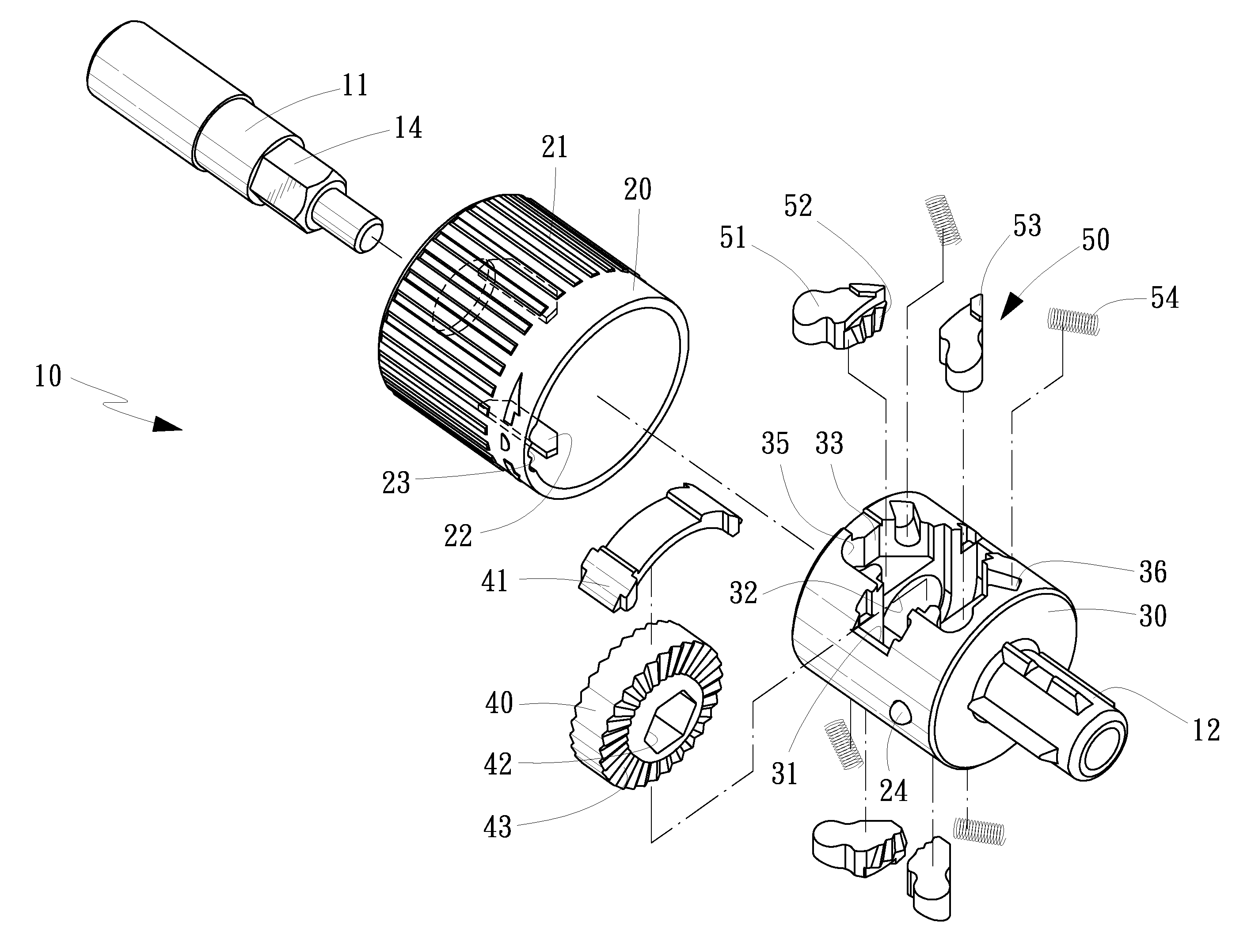
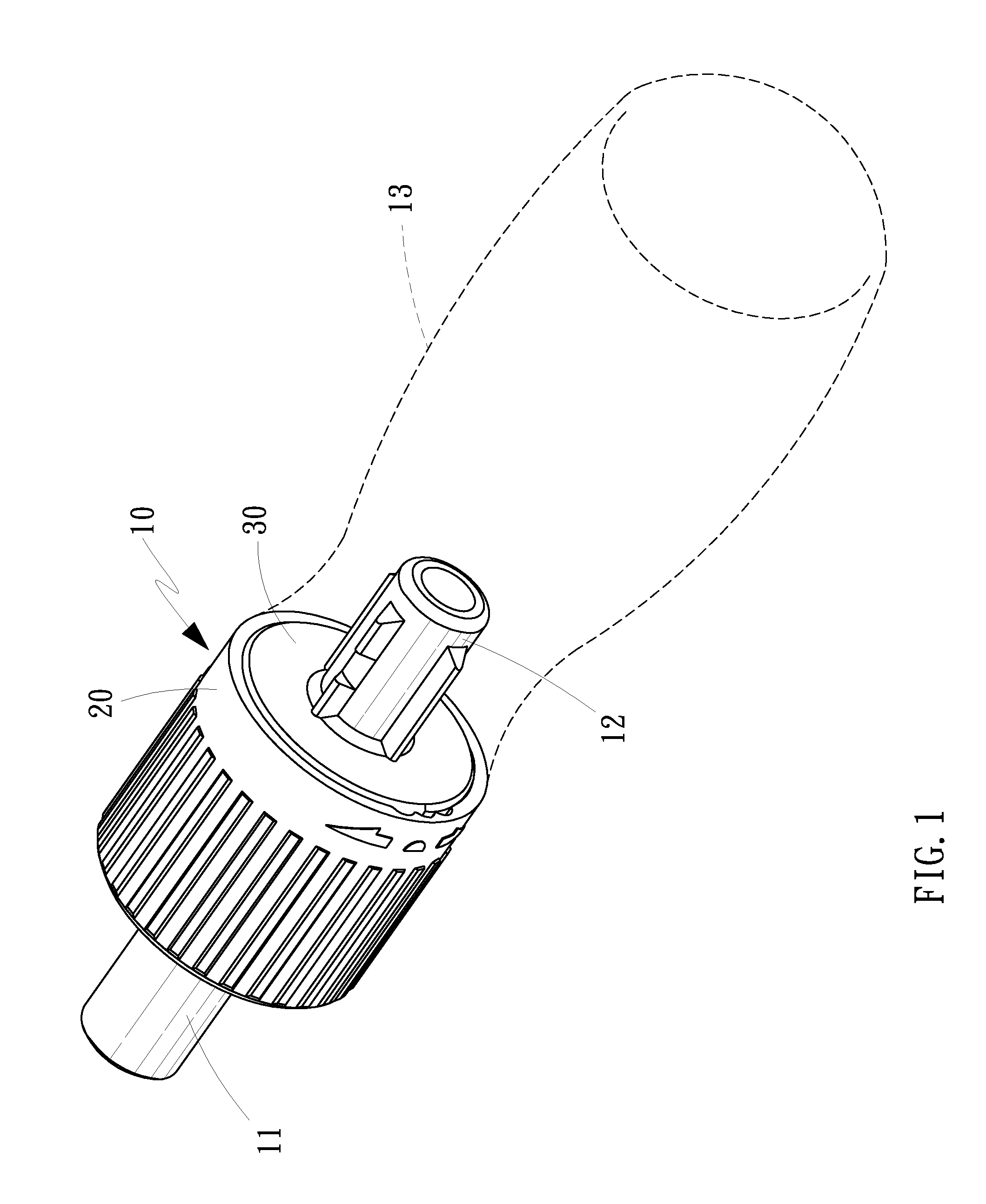
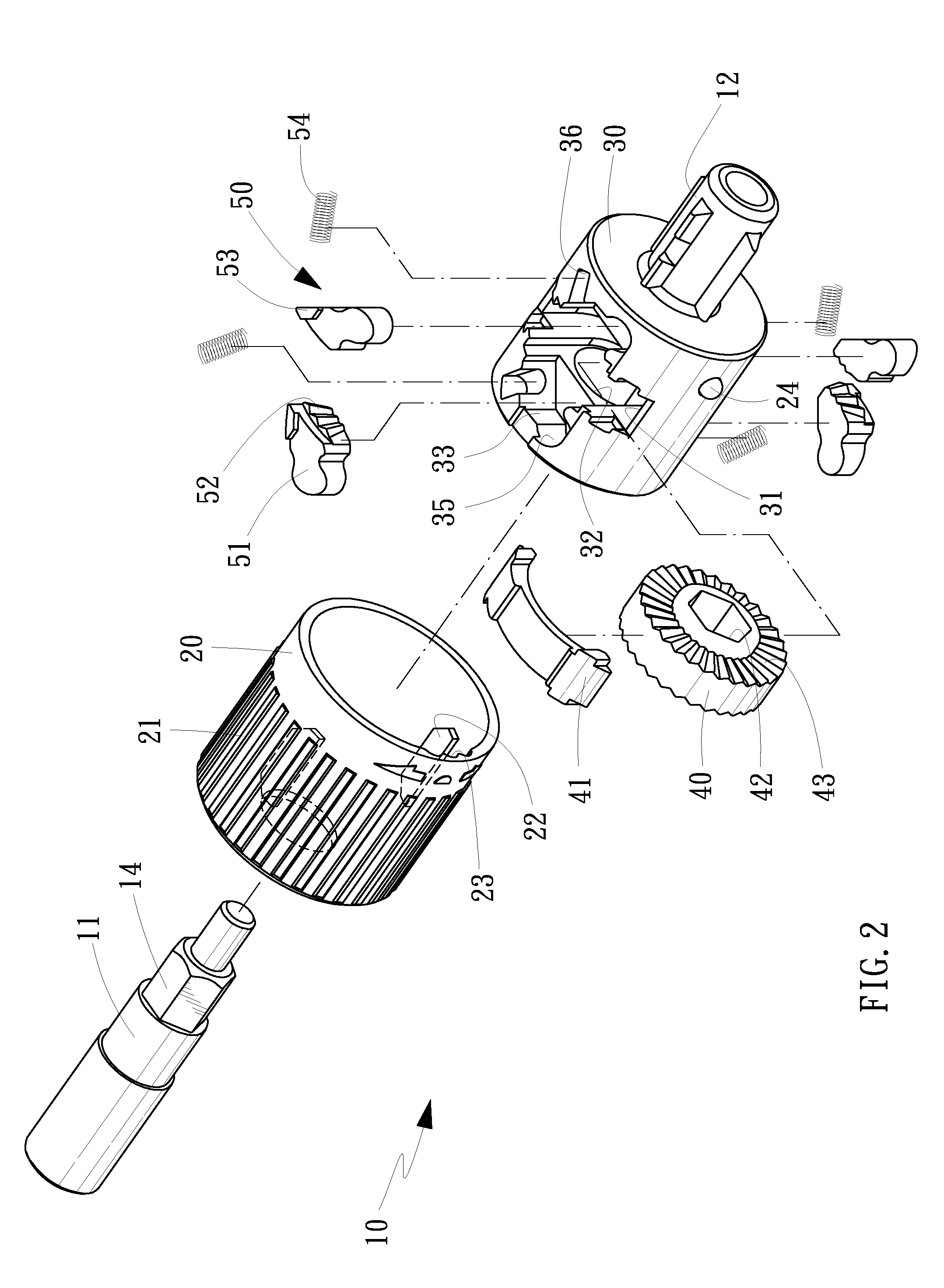
[0026]Referring to FIGS. 1 through 11, there is shown a screwdriver-used torque transmission apparatus 10 in accordance with a first embodiment of the present invention. The screwdriver-used torque transmission apparatus 10 includes a shaft 11, a shell 20, a frame 30, a gear 40, and two pairs of pawls 50 as shown in FIGS. 1 and 2.

[0027]The shaft 11 includes a non-circular cavity 15 axially defined in an end thereof and a non-circular shank 14 formed thereon near an opposite end thereof. The non-circular shank 14 is preferably a hexagonal shank. The non-circular cavity 15 is preferably a hexagonal cavity.

[0028]The shell 20 is a circular shell. The shell 20 includes ribs 21 extending on an external side thereof longitudinally, two pushers 22 formed on an internal side thereof, and three recesses 23 defined in the internal side thereof. The ribs 21 are used to increase friction thereof with a user's hand to facilitate the rotation of the shell 20. Each of the pushers 22 includes two ch...


PUM


Abstract

A screwdriver-used torque transmission apparatus includes a frame including a slot, an aperture and four cavities. The slot is in communication with the aperture and cavities. A gear includes a non-circular aperture axially defined therein, teeth formed on a side thereof, and teeth formed on an opposite end thereof. The gear is located in the slot. A pawl formed with at least one tooth and a block is located in each of the cavities. A shell includes two pushers formed on an internal side thereof. The shell is rotationally provided around the frame between two one-way modes in each of which a related one of the pushers pushes the blocks of two related ones of the pawls to disengage the teeth of the two pawls from the teeth of the gear.

Description

BACKGROUND OF INVENTION[0001]1. Field of Invention[0002]The present invention relates to a screwdriver and, more particularly, to an apparatus for transmitting torque to and a bit from a handle in a screwdriver.[0003]2. Related Prior Art[0004]There have been various hand tools. For example, screwdrivers or spanners are often used to drive screws or nuts.[0005]As disclosed in Taiwanese Patent Publication No. 17440, a conventional screwdriver includes a bit 1, handle 2 and a ring 3. The bit 1 includes two different operative tips. A selected one of the operative tips of the bit 1 is located outside the handle 2 while the unselected operative tip of the bit 1 is inserted in the handle 2. The ring 3 is engaged with the handle 2 to retain the unselected operative tip of the bit 1 in the handle 2. A user engages the selected operative tip of the bit 1 with a screw and then rotates the selected operative tip of the bit 1 in a first direction to rotate the screw in the first direction. Then...

Claims


Application Information

Patent Timeline
Patent Type & Authority Applications(United States)
IPC IPC(8): B25B15/04
CPCB25B15/04B25B13/466
Inventor LIN, JACK
Owner YIH CHENG FACTORY
Why Eureka
Try Eureka