
Methods and systems for avoiding a collision between an aircraft on a ground surface and an obstacle

a technology for ground surface collisions and aircraft, applied in the field of aircraft, can solve the problems of operator difficulty in monitoring aircraft extremes during ground operations, operator failure to detect obstacles located in “blind spots”, operator may only detect obstacles,

Active Publication Date: 2013-05-02
GULFSTREAM AEROSPACE CORP
View PDF17 Cites 55 Cited by
  • Summary
  • Abstract
  • Description
  • Claims
  • Application Information

AI Technical Summary

Benefits of technology

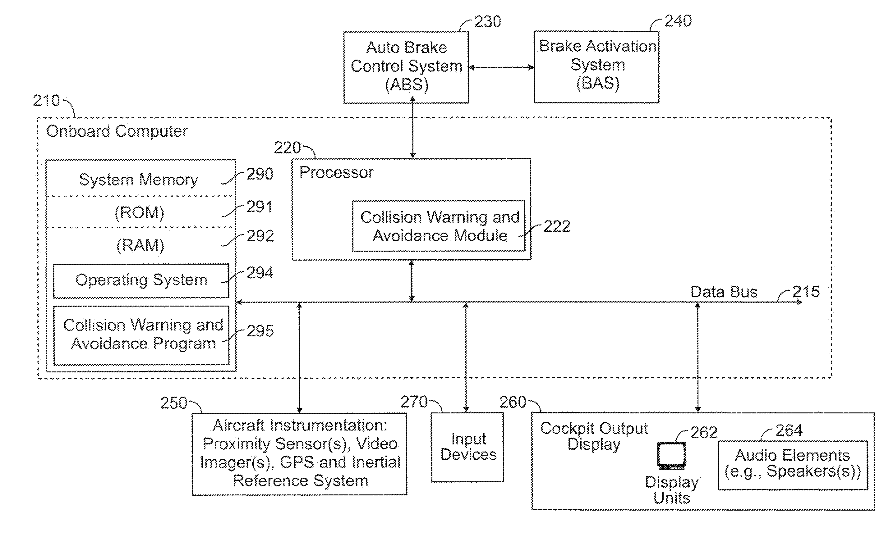
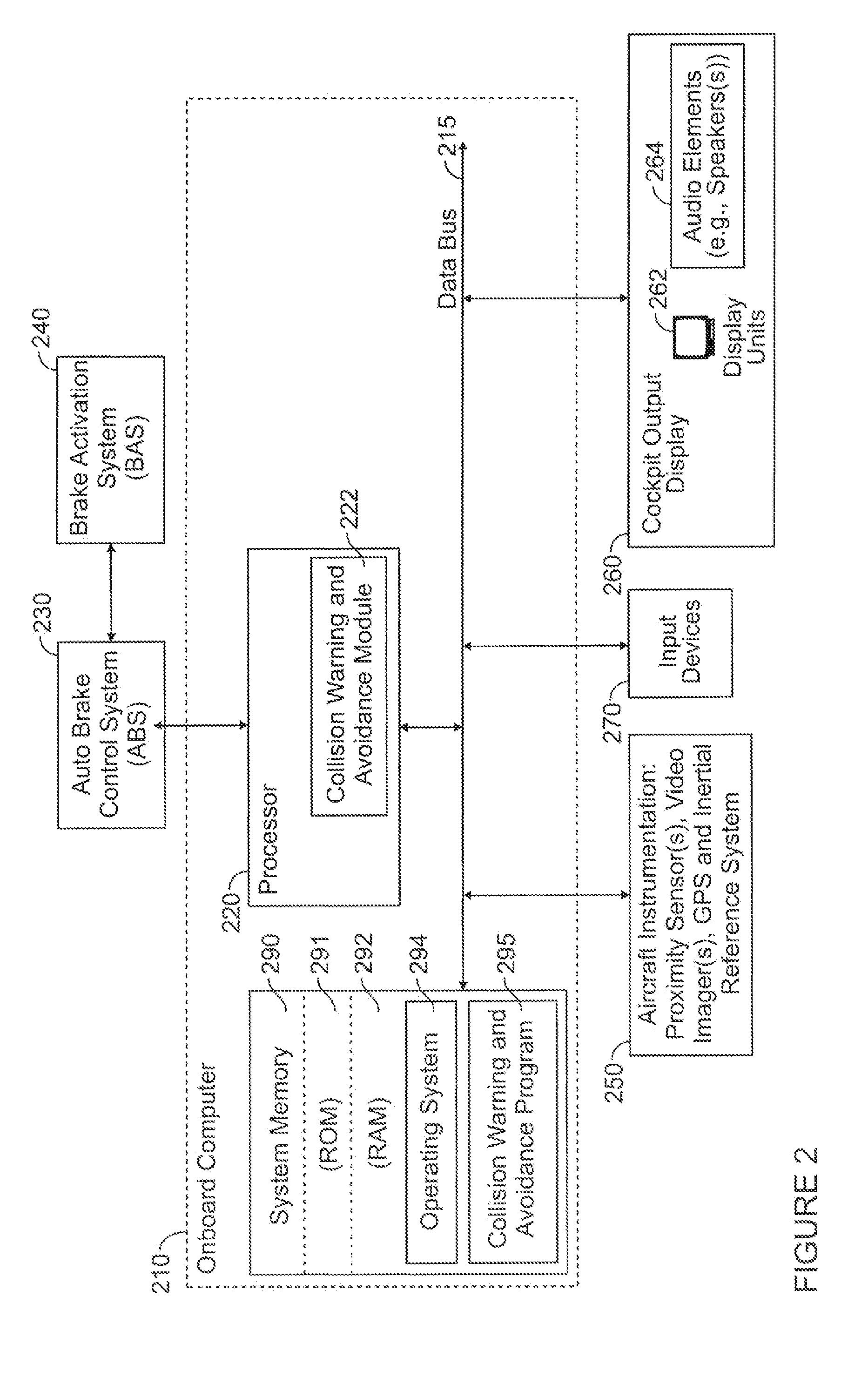
This patent is about a system that helps avoid collisions between aircraft and obstacles on the ground. The system uses proximity sensors and video imagers to detect if an obstacle is near the aircraft. When a sensor detects an obstacle, a computer sends a video image of the area around the aircraft to the cockpit, along with an alert signal and a brake activation signal. The system also allows the pilot to see the video image on a display in the cockpit. This system helps prevent accidents and ensures safety during ground operations.

Problems solved by technology

However, in many cases, due to the dimensions of the aircraft (e.g., large wing sweep angles, distance from cockpit to wingtip, etc.) and the operator's limited field of view of the areas surrounding the aircraft, it can be difficult for an operator to monitor extremes of the aircraft during ground operations.
As a result, the operator may fail to detect obstacles that are located in “blind spots” in proximity to the aircraft.
In many cases, the operator may only detect an obstacle when it is too late to take evasive action needed to prevent a collision with an obstacle.
Collisions with an obstacle can not only damage the aircraft, but can also put the aircraft out of service and result in flight cancellations.
The costs associated with the repair and grounding of an aircraft are significant.

Method used


Image

  • Methods and systems for avoiding a collision between an aircraft on a ground surface and an obstacle
  • Methods and systems for avoiding a collision between an aircraft on a ground surface and an obstacle
  • Methods and systems for avoiding a collision between an aircraft on a ground surface and an obstacle

Examples


Embodiment Construction

[0013]As used herein, the word “exemplary” means “serving as an example, instance, or illustration.” The following detailed description is merely exemplary in nature and is not intended to limit the invention or the application and uses of the invention. Any embodiment described herein as “exemplary” is not necessarily to be construed as preferred or advantageous over other embodiments. All of the embodiments described in this Detailed Description are exemplary embodiments provided to enable persons skilled in the art to make or use the invention and not to limit the scope of the invention which is defined by the claims. Furthermore, there is no intention to be bound by any expressed or implied theory presented in the preceding technical field, background, brief summary or the following detailed description.

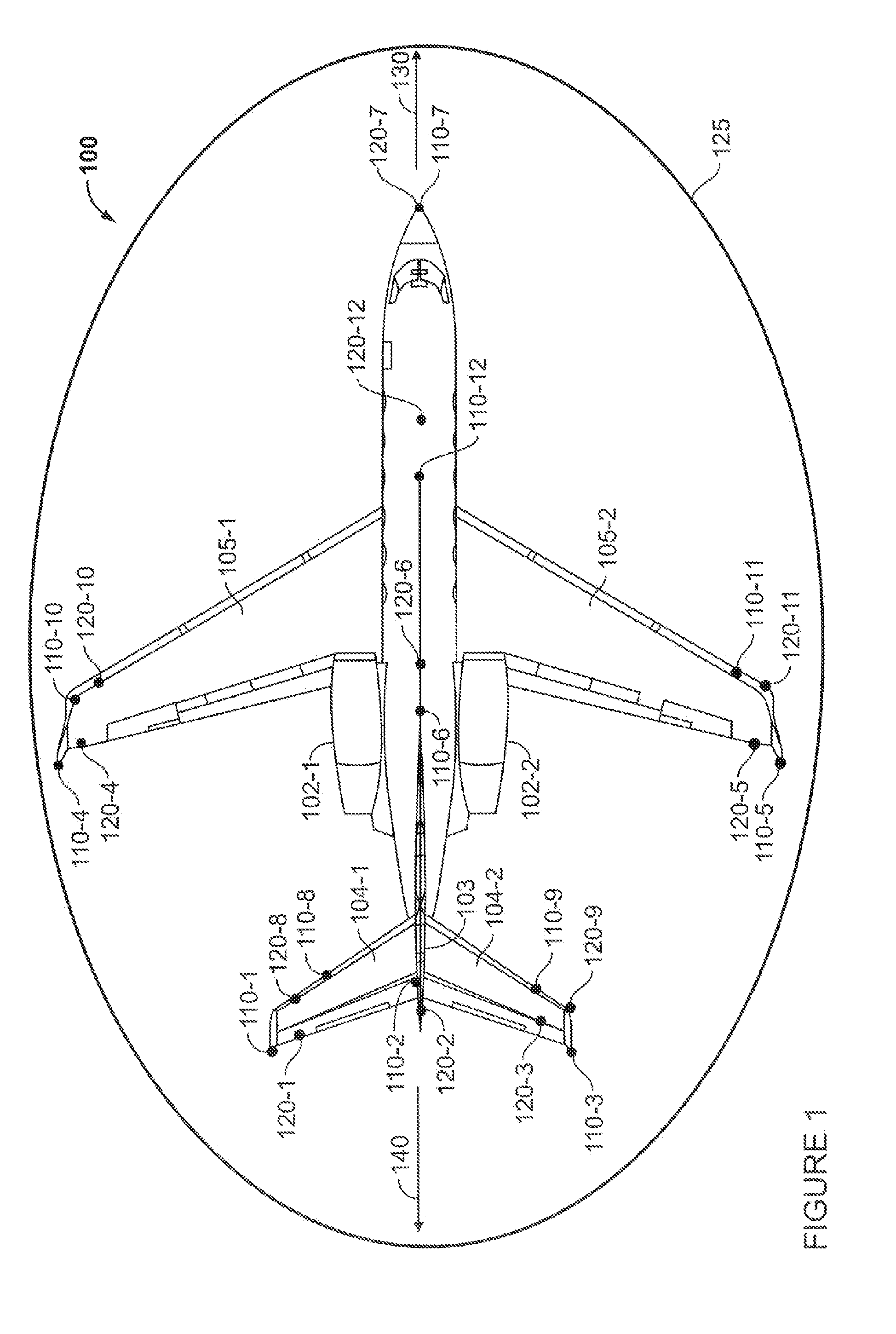
[0014]FIG. 1 is a top view of an aircraft 100 that includes instrumentation for implementing a collision warning and avoidance system in accordance with some of the disclosed emb...


PUM


Abstract

The disclosed embodiments relate to methods and systems for avoiding a collision between an obstacle and a vehicle, such as an aircraft, on a ground surface. A processor receives a detection signal from one of a plurality of proximity sensors. The detection signal indicates that the obstacle has been detected. In response to receiving the detection signal, a video image signal is transmitted from the processor to a display in the cockpit of the aircraft. The video image signal corresponds to a particular video imager that is associated with the particular proximity sensor that detected the obstacle. A video image, of a particular region around the aircraft that includes the obstacle is displayed on a display. In response to receiving the detection signal, the processor can also transmit an alert signal, and a brake activation signal to activate a braking system to prevent the aircraft from colliding with the obstacle.

Description

TECHNICAL FIELD[0001]Embodiments of the present invention generally relate to aircraft, and more particularly relate to methods and systems for avoiding collisions between an aircraft on a ground surface and an obstacle.BACKGROUND OF THE INVENTION[0002]An operator of an aircraft must often maneuver the aircraft while on the ground. This may happen during ground operations such as when the aircraft is taxiing, being maneuvered to or from a hangar, or backing an aircraft away from a terminal.[0003]Obstacles on the ground, such as structures, other vehicles and other obstacles, may lie in the path of a vehicle. These obstacles can be detected by a person using their sense of sight. However, in many cases, due to the dimensions of the aircraft (e.g., large wing sweep angles, distance from cockpit to wingtip, etc.) and the operator's limited field of view of the areas surrounding the aircraft, it can be difficult for an operator to monitor extremes of the aircraft during ground operation...

Claims


Application Information

Patent Timeline
Patent Type & Authority Applications(United States)
IPC IPC(8): G08G5/04G08G9/02B60T7/12G01S13/93G01S13/931G01S13/934G01S15/93G01S17/93G01S17/933
CPCG01S13/93G08G5/0021G08G5/065G05D1/0083G05D1/0202G05D1/0231G01S15/08G05D1/0259G01S15/93G01S17/08G01S17/93G01S13/08G05D1/0255G01S17/933G01S7/24G01S7/51G01S7/56G01S13/934G01S2013/93185G01S2013/9323G01S2013/9324B64D47/08G01S13/931B64C25/44G08G5/04H04N7/181
Inventor KNIGHT, MICHAEL
Owner GULFSTREAM AEROSPACE CORP
Learn More