Gas distributor for granular moving-bed filter

a technology of moving-bed filters and distributors, which is applied in the direction of transportation and packaging, lighting and heating equipment, separation processes, etc., can solve the problems of contaminated gas flow blocking, affecting the environment of our world, and much more easily clogged

Inactive Publication Date: 2013-04-25
INST NUCLEAR ENERGY RES ROCAEC
View PDF7 Cites 3 Cited by
  • Summary
  • Abstract
  • Description
  • Claims
  • Application Information

AI Technical Summary

Benefits of technology

The present invention provides a gas distributor that is designed to prevent dust or contaminants from being concentratedly deposited at certain inlets of a granular moving-bed filter and clogging them. This is achieved through the use of a distribution module that includes a flow-distributing curtain that transforms the turbulent gas flow into a more uniformly distributed gas flow while preliminarily filtering out dust. Additionally, the gas distributor includes a vibrator that can strip off dust or contaminants from the distribution module, enabling it to be cleaned without stopping the operation of the distribution module when the inlets of the granular moving-bed filter are clogged by dust.

Problems solved by technology

Coal-fired thermal power plants or incineration plants generate high-temperature gas containing a large amount of fly ash (dust), sulfides, nitrides or other contaminants, and if the exhaust flue gas or raw synthesis gas is emitted without processing, the environment of our world will be affected seriously.
However, since the contaminated gas is, in most case, not uniformly distributed while being fed into and flow inside a granular moving-bed filter, it is common that the majority of the contaminated gas will concentrate to flow through a certain part of the granular moving-bed filter while allowing the other part of the granular moving-bed filter to receive only a minute portion of the contaminated gas, and thereby, the part of the granular moving-bed filter where the majority of the contaminated gas is concentrated will be much more easily to be clogged by dust and contaminants contained in the contaminated gas comparing with the other parts, and eventually the flow of the contaminated gas will be blocked in a way that the filtration efficiency of the granular moving-bed filter will be severely affected.

Method used


Image

  • Gas distributor for granular moving-bed filter
  • Gas distributor for granular moving-bed filter
  • Gas distributor for granular moving-bed filter

Examples


first embodiment

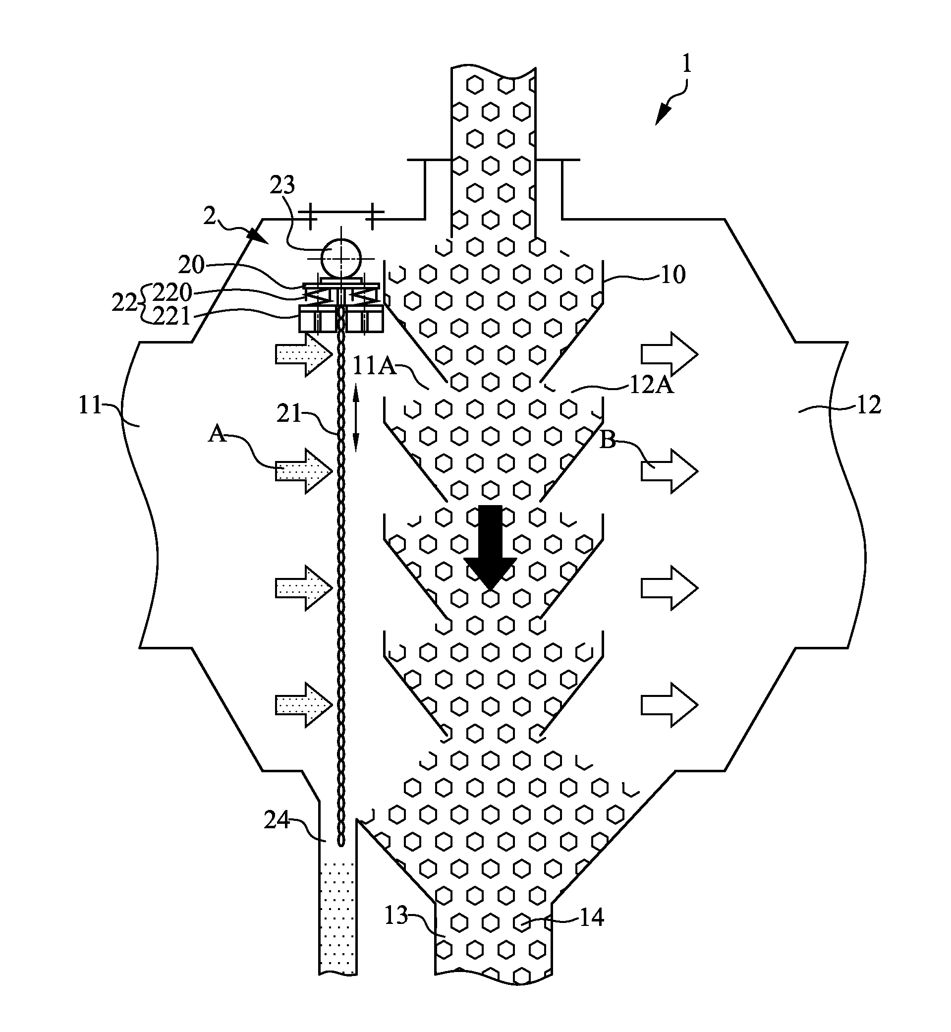
[0030]Please refer to FIG. 1, which is a schematic diagram showing a gas distributor for a granular moving-bed filter according to the invention. As shown in FIG. 1, a gas distributor is adapted for a granular moving-bed filter 1, which comprises: an inlet 11 disposed at a side of the granular moving-bed filter for allowing a dust-containing gas flow A passing therein, an outlet 12 disposed at another side of the granular moving-bed filter 1, and a plurality of hopper structures 10 longitudinally arranged and stacked inside the granular moving-bed filter 1 while being in communication with each other for forming a longitudinal channel 13 having filter granules 14 flowing therethrough. Moreover, each hopper structure 10 in the granular moving-bed filter 1 is configured with at least one inlet 11A at a side corresponding to the inlet 11 and at least one outlet 12A at a side corresponding to the outlet 12.

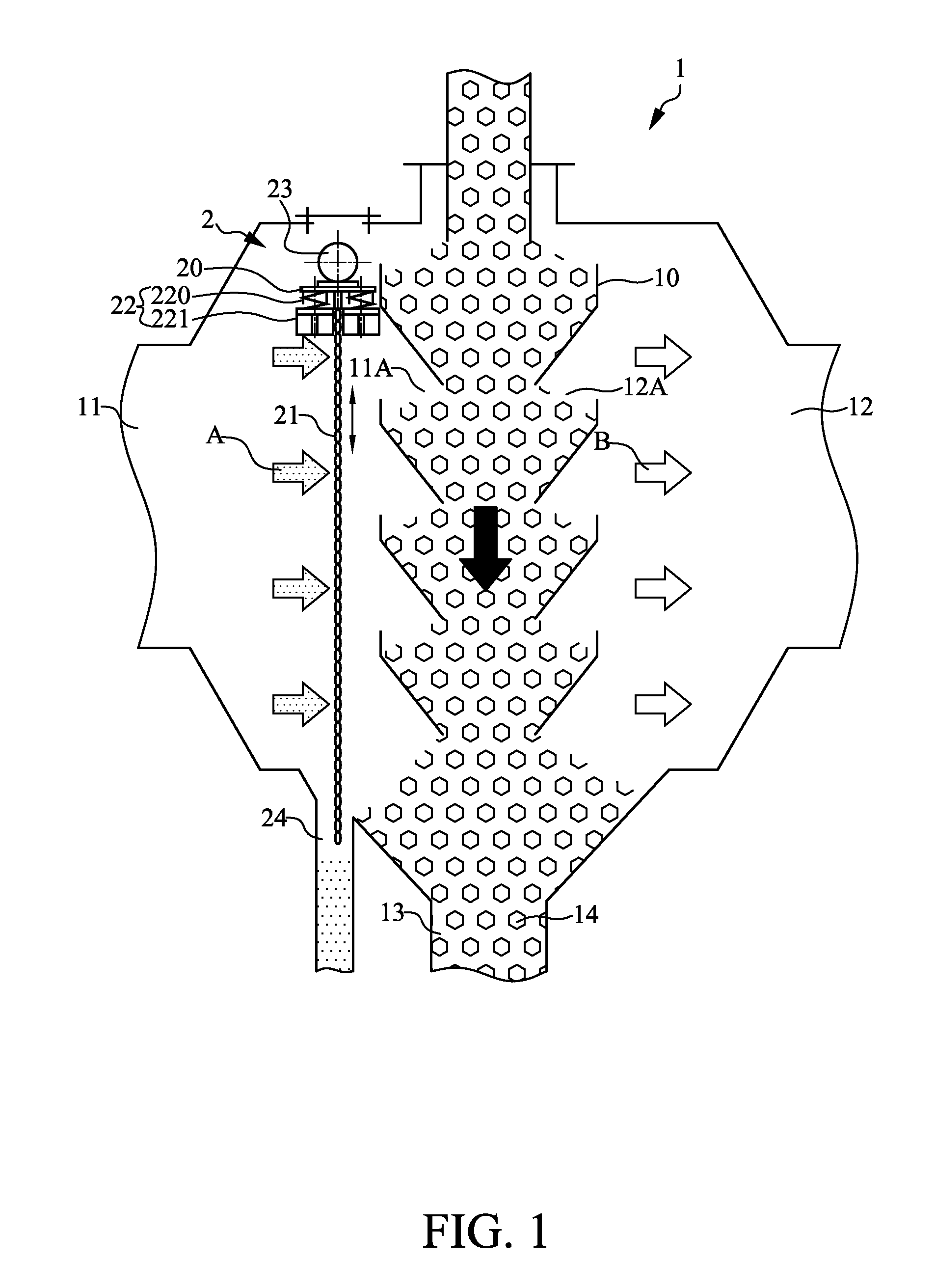
[0031]In addition, the gas distributor has a distribution module 2, which compris...

second embodiment

[0037]Please refer to FIG. 3, which is a schematic diagram showing a flow-distributing curtain used in a gas distributor of the invention.

[0038]In this second embodiment, the flow-distributing curtain 21A is composed of a plurality of ropes 210A while allowing a flow-through area 212A to be formed between any two neighboring ropes 210A, resulting that the flow-distributing curtain 21A is formed with a plurality of flow-through areas 212A.

[0039]Please refer to FIG. 4, which is a schematic diagram showing a flow-distributing curtain used in a gas distributor of a third embodiment of the invention. In this third embodiment, the flow-distributing curtain 21B is composed of a plurality of bar-like elements 210B while allowing a flow-through area 212B formed between any two neighboring bar-like elements 210B, resulting that the flow-distributing curtain 21B is formed with a plurality of such flow-through areas 212B. Moreover, each bar-like element 210B is an object selected from the group...

fifth embodiment

[0041]Please refer to FIG. 6 and FIG. 7, which are schematic diagrams showing the gas distributor of the In this embodiment, there are a plurality of second dampers 25 being disposed at the top of the support 20 while simultaneously there are a plurality of first dampers 22 being disposed at the bottom of the support 20, and also in addition to the vibrator 23 that is arranged at the top of the support 20, there is an additional vibrator 230 being arranged at the bottom of the support 20. It is noted that any one of the first dampers 22 and second dampers 25 can be an industrial damper or damper that is currently available on the market, and thus it is not restricted by those disclosed on the figures of the present invention.

[0042]As shown in FIG. 7, each second damper 25 is disposed at the top of the support 20 on a side thereof, and is composed of a second seat 251 and an elastic member 250 in a manner that the second seat 251 is mounted on the top of the support 20; and an end o...


PUM

PropertyMeasurementUnit
Timeaaaaaaaaaa
Poweraaaaaaaaaa
Areaaaaaaaaaaa

Abstract

A gas distributor for a granular moving-bed filter comprises a distribution module, arranged inside a granular moving-bed filter. The distribution module comprises at least one flow-distributing curtain to be used for allowing a turbulent gas flow with dust mixed therein to flow therethrough, resulting that before the turbulent gas flow enters the granular moving-bed filter, the turbulent gas flow is transformed into a more uniformly distributed gas flow and the dust contained therein are partially filtered out.

Description

FIELD OF THE INVENTION[0001]The present invention relates to a gas distributor for granular moving-bed filter, and more particularly, to a gas distributor for processing a turbulent gas flow containing ash or dust before entering the granular moving-bed filter so that the turbulent gas flow can become more uniformly distributed while the ashes or dust contained therein can be partially filtered out.BACKGROUND OF THE INVENTION[0002]Coal-fired thermal power plants or incineration plants generate high-temperature gas containing a large amount of fly ash (dust), sulfides, nitrides or other contaminants, and if the exhaust flue gas or raw synthesis gas is emitted without processing, the environment of our world will be affected seriously.[0003]According to foregoing mentioned problems, the industrial countries have to determine strict emission standards, and meanwhile, also have to input considerable research and development (R&D) resources to investigate how to remove the harmful pollut...

Claims


Application Information

Patent Timeline
IPC IPC(8): F16L41/00
CPCF23J15/025F23J2217/105F23J2217/20F23J2217/30B01D46/0053B01D46/34B01D46/0075B01D46/32B01D45/08Y10T137/85938B01D46/76
Inventor CHYOU, YAU-PINSMID, JIRICHEN, PO-CHUANGCHEN, YI-SHUNLI, SHU-CHEHSIAU, SHU-SAN
Owner INST NUCLEAR ENERGY RES ROCAEC
Why Eureka
Try Eureka