Eureka AIR delivers breakthrough ideas for toughest innovation challenges, trusted by R&D personnel around the world.

Method of, and device for, marking a patient's eye for reference during a toric lens implantation procedure

a toric lens and eye reference technology, applied in the field of toric lens implantation procedures, can solve the problems of large cylindrical correction, increased error, and increased thickness of the marker, and achieve the effect of minimal eccentric reference marks and small thickness

Active Publication Date: 2013-04-18
BEAVER VISITEC INT US
View PDF14 Cites 3 Cited by
  • Summary
  • Abstract
  • Description
  • Claims
  • Application Information

AI Technical Summary

Benefits of technology

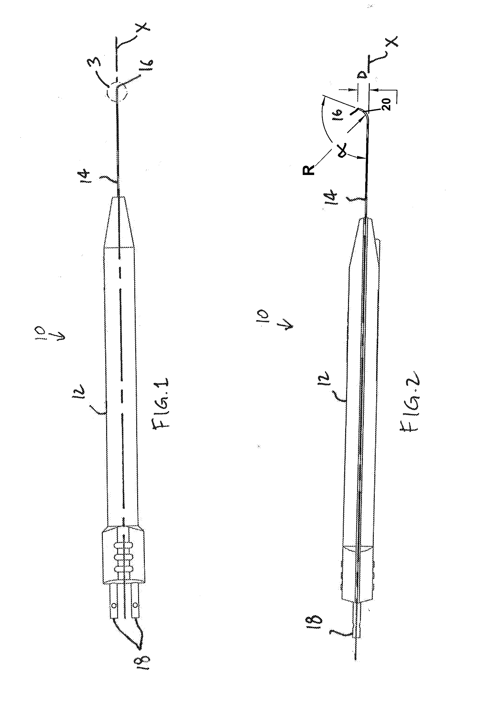
The patent is about an electrocautery device that has a specific shape to it. This shape allows for smaller and more accurate reference marks to be made during a procedure. The device can be either straight or bent / curved, and the specific shape range provided in the patent makes it easier to use for both types of devices.

Problems solved by technology

Commonly, a surgical marking pen is used to make the reference marks However, the thickness of the marker adds error and the ink of the mark is likely to diffuse, fade or disappear as it mixes with the tears from the patient's eye.
Every degree of inaccuracy in the placement of a toric lens reduces the amount of cylindrical correction by approximately three percent, Thus, inaccurate or fading reference marks may present difficulties in achieving the most accurate placement of the tonic lens.
The straightness of the shaft of the electrocautery device, however, may be cumbersome for some due to the roundness of the patient's eye.
Because of the straightness of the shaft, the device may be difficult to handle during marking.

Method used


Image

  • Method of, and device for, marking a patient's eye for reference during a toric lens implantation procedure
  • Method of, and device for, marking a patient's eye for reference during a toric lens implantation procedure
  • Method of, and device for, marking a patient's eye for reference during a toric lens implantation procedure

Examples


Embodiment Construction

[0017]With reference to the figures, an electrocautery device 10 is shown which generally includes a handle 12, a shaft 14 extending from the handle 12, and a tip 16 defined at the terminus of the shaft 14, The device 10 is particularly well-suited for use during a toric lens implantation procedure, as described herein, but may have application elseWhere, as will be appreciated by those skilled in the art.

[0018]The device 10 is configured to cauterize tissue upon sufficient contact with the tip 16. Various electrocautery devices are known in the art including devices sold under the tradename “WET-FIELD® ERASER®” by Beaver-Visitec International, Inc. of Waltham, Mass. The device 10 may, be provided with bipolar diathermy capability, or other features, The shaft 14, including the tip 16, may be provided in various gauges, but preferably a smaller-diameter gauge is provided, such as a 20-27 gauge, more preferably, a 23-25 gauge, and even more preferably, a 25 gauge design is provided. ...


PUM


Abstract

In one aspect, a method is provided herein of marking a patient's eye for reference during a tonic lens implantation procedure. The method includes providing an electrocautery device having a handle, a shaft extending from the handle, and a tip defined at the terminus of the shaft. The handle is elongated and extends along a longitudinal axis with the shaft being bent or curved such that the tip is spaced from, and not aligned with, the longitudinal axis. The method further includes using the electrocautery device to cauterize one or more points on the patient's eye, the points being located as reference marks for placement of the toric lens. Advantageously, with the subject invention, a device is used having a bent or curved shaft Which may better accommodate the curvature of a patient's eye While marking.

Description

CROSS-REFERENCE TO RELATED APPLICATION[0001]This application claims priority to U.S. Provisional Patent Application No. 61 / 547,877, filed Oct. 17, 2011, the entire contents of which are incorporated by reference herein.FIELD OF THE INVENTION[0002]A method, and device, are provided herein useable for marking a patient's eye for reference during a tonic lens implantation procedure.BACKGROUND OF THE INVENTION[0003]Tonic lens implantation is known in the art to replace the natural lens of the eye. A toric lens is a replacement intraocular lens (TOL) used for cataract patients with pre-existing astigmatism. The correct angular position of a tonic lens is a criticai component in order to maximize the amount of astigmatic correction. To assist in proper placement, at least one reference mark is made on the eye, preferably on or near the limbus, to define a horizontal reference axis. Using the reference mark(s), alignment mark(s) are subsequently prepared to properly align the tonic lens In...

Claims


Application Information

Patent Timeline
Patent Type & Authority Applications(United States)
IPC IPC(8): A61B18/08
CPCA61F9/007A61B18/1402A61B2018/1432A61B18/1477A61B2018/1422A61F2002/1645A61F2/1645
Inventor OSHER, ROBERT H.MURRAY, COLLIN ALEXANDER
Owner BEAVER VISITEC INT US
Why Eureka
Eureka Blog
Learn More