
Storage rack

a storage rack and rack technology, applied in the field of storage devices, can solve the problems of poor arrangement of bags for convenient service, and achieve the effect of convenient holding stably boxes or bags, and being convenient to manufactur

Inactive Publication Date: 2013-04-18
CHEN FANG YIN
View PDF24 Cites 19 Cited by
  • Summary
  • Abstract
  • Description
  • Claims
  • Application Information

AI Technical Summary

Benefits of technology

The present invention is a storage rack that is cheap to make and can hold boxes or bags of goods securely.

Problems solved by technology

Further, when storing bagged products, such as tea bags or coffee bags in a box, the bagged products may be not arranged in a good order for convenient service.

Method used


Image

  • Storage rack
  • Storage rack
  • Storage rack

Examples


Embodiment Construction

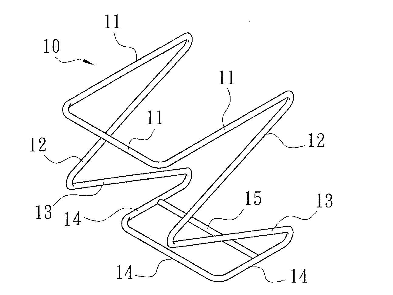
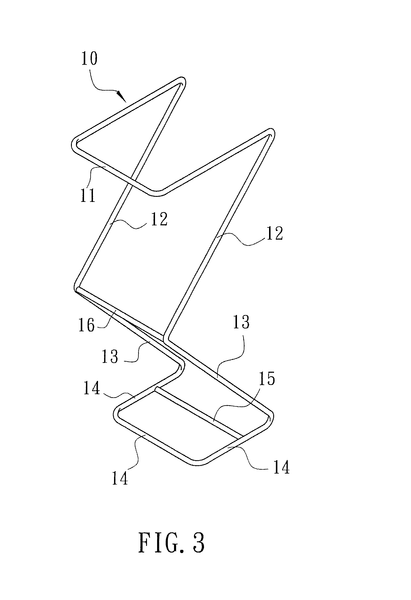
[0014]Referring to FIG. 1, a storage rack 10 in accordance with a first embodiment of the present invention is made of metal wire rods, comprising a U-shaped top constraint rod 11, a U-shaped bottom positioning rod 14, two oblique upper side rods 12 respectively forwardly extended from the two distal ends of the U-shaped top constraint rod 11, two oblique lower side rods 13 respectively backwardly extended from the bottom ends of the two oblique upper side rods 12 and respectively connected to the two distal ends of the U-shaped bottom positioning rod 14, and a transverse rod 15 transversely connected between the two distal ends of the U-shaped bottom positioning rod 14 to reinforce the structural strength. According to this first embodiment, the U-shaped top constraint rod 11 and the U-shaped bottom positioning rod 14 are horizontally arranged at different elevations in a parallel manner.

[0015]Referring to FIG. 2 and FIG. 1 again, a box 1 holding a stack of cap-like products 2 ther...


PUM


Abstract

A storage rack includes a U-shaped top constraint rod, a U-shaped bottom positioning rod, two oblique upper side rods respectively forwardly extended from two distal ends of the U-shaped top constraint rod, two oblique lower side rods respectively backwardly extended from respective bottom ends of the two oblique upper side rods and respectively connected to two distal ends of the U-shaped bottom positioning rod, and a transverse rod transversely connected between the two distal ends of the U-shaped bottom positioning rod.

Description

BACKGROUND OF THE INVENTION[0001]1. Field of the Invention[0002]The present invention relates to storage devices and more particularly, to a simple structure of storage rack, which is inexpensive to manufacture and practical for holding a box or a set of bags stably.[0003]2. Description of the Related Art[0004]Conventionally, people usually use a box to keep cap-like products (such as coffee balls, milk balls, coffee mate balls). The box has a bottom access hole through which a person can pull each individual storage item out of the box. When taking one storage item out of the box, the user must hold the box with one hand and then pull one storage item out of the box with the other hand. Further, when storing bagged products, such as tea bags or coffee bags in a box, the bagged products may be not arranged in a good order for convenient service.SUMMARY OF THE INVENTION[0005]The present invention has been accomplished under the circumstances in view. It is one object of the present i...

Claims


Application Information

Patent Timeline
Patent Type & Authority Applications(United States)
IPC IPC(8): A47F5/01
CPCA47F1/082A47F5/01
Inventor CHEN, FANG-YIN
Owner CHEN FANG YIN
Learn More