Filter device, image decoding device, image encoding device, and filter parameter data structure
a filter device and image encoding technology, applied in the field of filter devices, image encoding devices, image encoding devices, and filter parameter data structures, can solve the problems of encoding noise, block noise, and block noise, and achieve high coding efficiency, reduce at least the volume of processing or processing time, and reduce the effect of processing volum
- Summary
- Abstract
- Description
- Claims
- Application Information
AI Technical Summary
Benefits of technology
Problems solved by technology
Method used
Image

Examples
embodiment 1
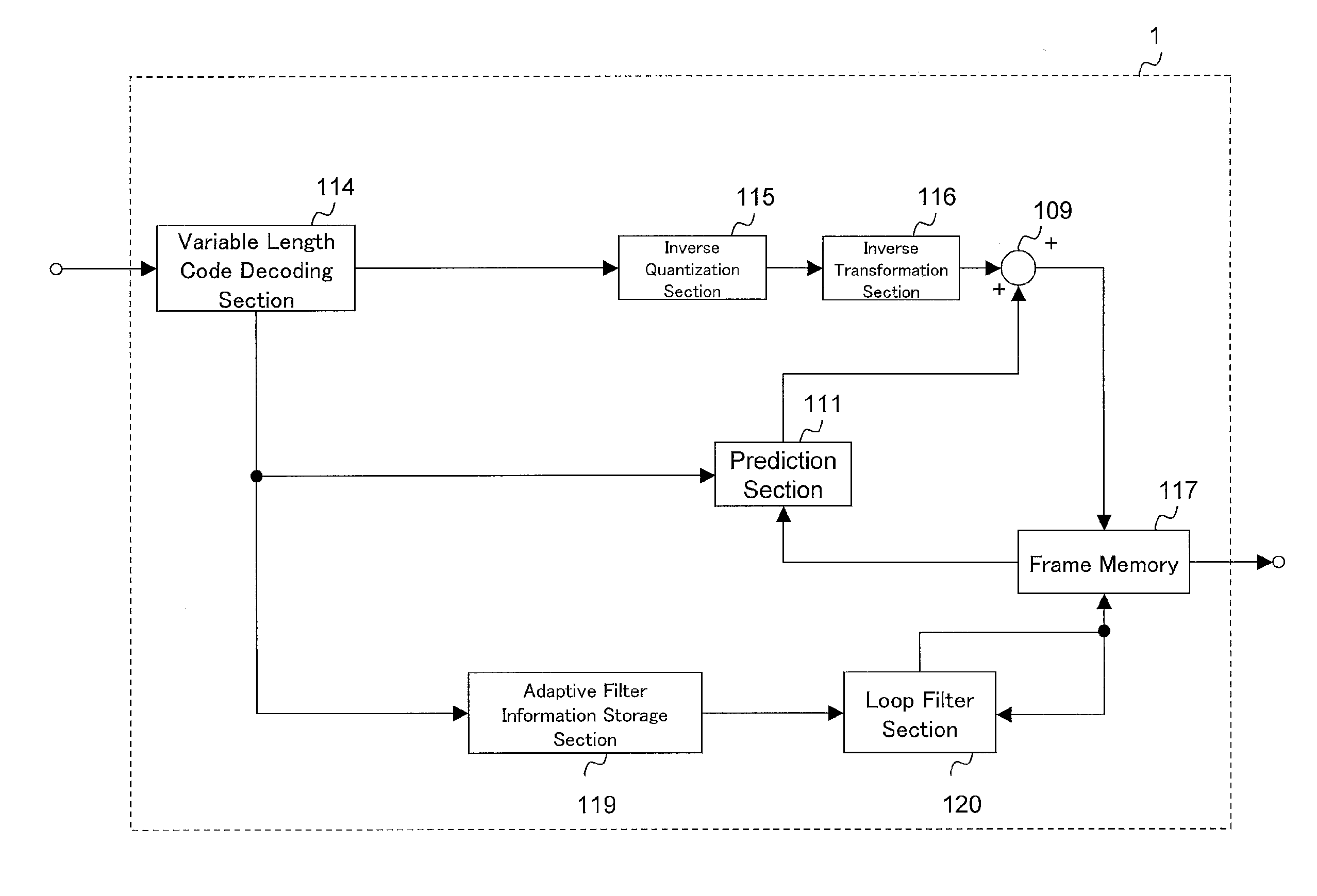
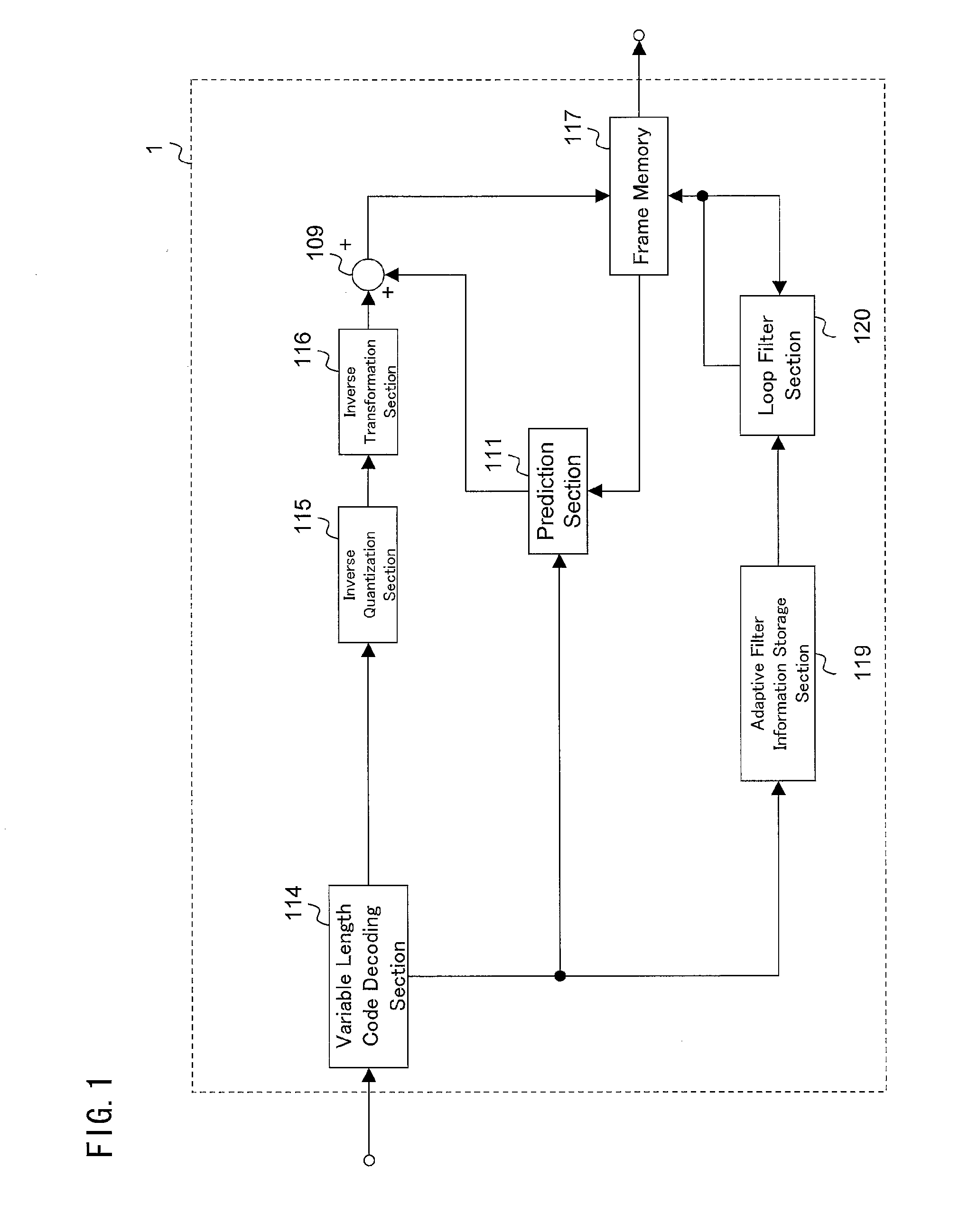
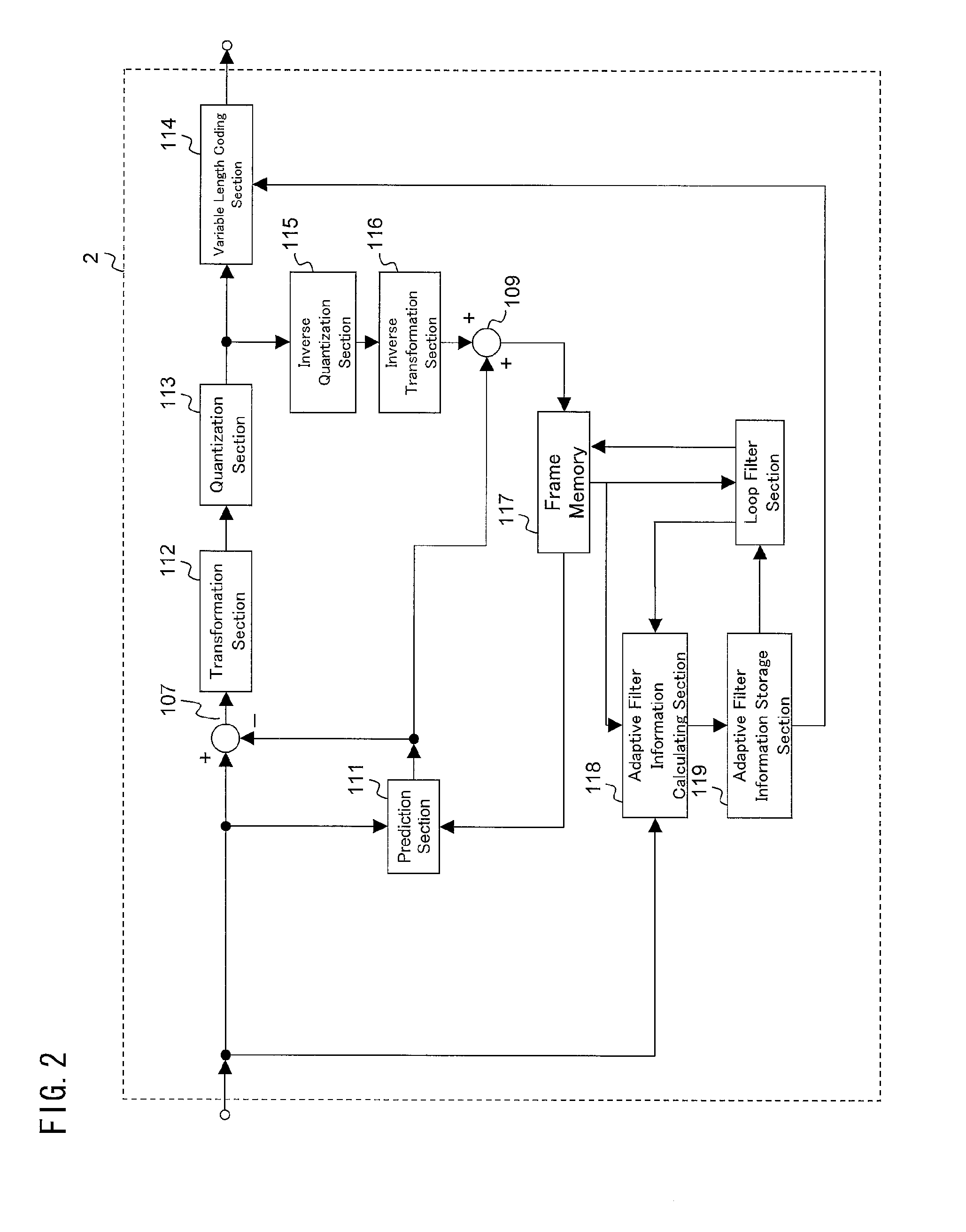
[0095]Prior to a description of a moving image decoder 1 according to a first embodiment of the present invention, a structure of coded data that is generated by a moving image encoder 2 according to the present embodiment and decoded by the moving image decoder 1 is described with reference to FIG. 11.
[0096]The coded data is constituted by a series of image data (pictures). As shown in FIG. 11, each single picture is constituted by a plurality of slices. Each slice is constituted by adaptive filter information and MB data. The MB data is information for generating a decoded image, and is constituted by a block type, a prediction block size, a prediction parameter, a transform block size, and residual information.
[0097]The adaptive filter information is information which, in a frame memory having decoded images stored therein, is used to control an adaptive filter process, and is constituted by on-off information for controlling a filter so that the filer is on or off, a tap number ...
modified example 1
[0306]A first modified example of the loop filter section 120 shown in FIG. 20 will be described with reference to FIGS. 21 and 22.
[0307]A loop filter section 120a according to the present modified example is a filter device operable in (1) a first mode where an output image S2 supplied from the second linear filter section 702 serves as an output image S and in (2) a second mode where a synthetic image S, which is obtained by adding the output image S1 of the first linear filter section 701 and the output image S2 of the second linear filter section 702, serves as an output image S.
[0308]Whether the loop filter section 120a operates in the first mode or in the second mode is controlled by mode specification information (hereinafter also represented as “alf_parallel_mode”) included in a filter parameter which is provided by the moving image encoder 2. In the present modified example, the loop filter section 120a operates in the first mode when the alf_parallel_mode=0 (zero), while t...
modified example 2
[0323]Next, a second modified example of the loop filter section 120 shown in FIG. 20 will be described with reference to FIG. 23.
[0324]A loop filter section 120b according to the present modified example is a filter device operable in (1) a first mode where an upper limit value settable for a tap number N of a second linear filter section 702 is not determined, and (2) a second mode where the upper limit value settable for the tap number N of the second linear filter section 702 is determined to Nmax. The tap number N of the second linear filter section 702 is not determined to a value larger than Nmax in the second mode. That is, the second linear filter section 702 does not carry out an excessively heavy-load filtering operation in the second mode.
[0325]Whether the loop filter section 120b operates in the first mode or in the second mode is controlled by mode specification information (which is represented herein by “alf_parallel_mode”) included in a filter parameter to be suppli...
PUM
 Abstract
Description
Claims
Application Information
 - R&D
- Intellectual Property
- Life Sciences
- Materials
- Tech Scout
- Unparalleled Data Quality
- Higher Quality Content
- 60% Fewer Hallucinations
Browse by: Latest US Patents, China's latest patents, Technical Efficacy Thesaurus, Application Domain, Technology Topic, Popular Technical Reports.
© 2025 PatSnap. All rights reserved.Legal|Privacy policy|Modern Slavery Act Transparency Statement|Sitemap|About US| Contact US: help@patsnap.com