
Sprinkler Structure

a technology of sprayer and nozzle, which is applied in the direction of spraying apparatus, spraying nozzle, movable spraying apparatus, etc., can solve the problems of uneven spraying, unfavorable improvement of uneven spraying drawback, and the discovery of drawbacks

Inactive Publication Date: 2013-03-28
RUEY RYH ENTERPRISE
View PDF5 Cites 5 Cited by
  • Summary
  • Abstract
  • Description
  • Claims
  • Application Information

AI Technical Summary

Benefits of technology

The present invention is a sprinkler structure that improves upon prior art by including a shell base with a water inlet hole, a water nozzle, a water conveyance element, an eccentric gear device, a drive gear device, a spray angle adjusting element, a supporting bracket, a limit protrusion, and a drive bar. The structure also includes a fixing base for fixing the water nozzle and the shell base. The eccentric gear device includes an eccentric gear and a drive gear device hole, and the drive gear device is connected to the eccentric gear. The structure allows for continuous adjustment of the water outlet surface within a limited range. The water conveyance element conveys water from the water inlet hole to the water nozzle. The spray angle adjusting element is fixed on the water nozzle and is rotatable. The water conveyance element includes a water conveyance pipe and a cam driven by the eccentric gear. The drive gear device includes a turbine component and a coupling gear. The structure also includes uni-directional gear components and a drive gear device hole. The fixing base includes a first and second fixing axle and a first and second fixing sleeve component. The technical effects of the present invention include improved water outlet surface coverage, improved water flow control, and improved spray angle adjustment.

Problems solved by technology

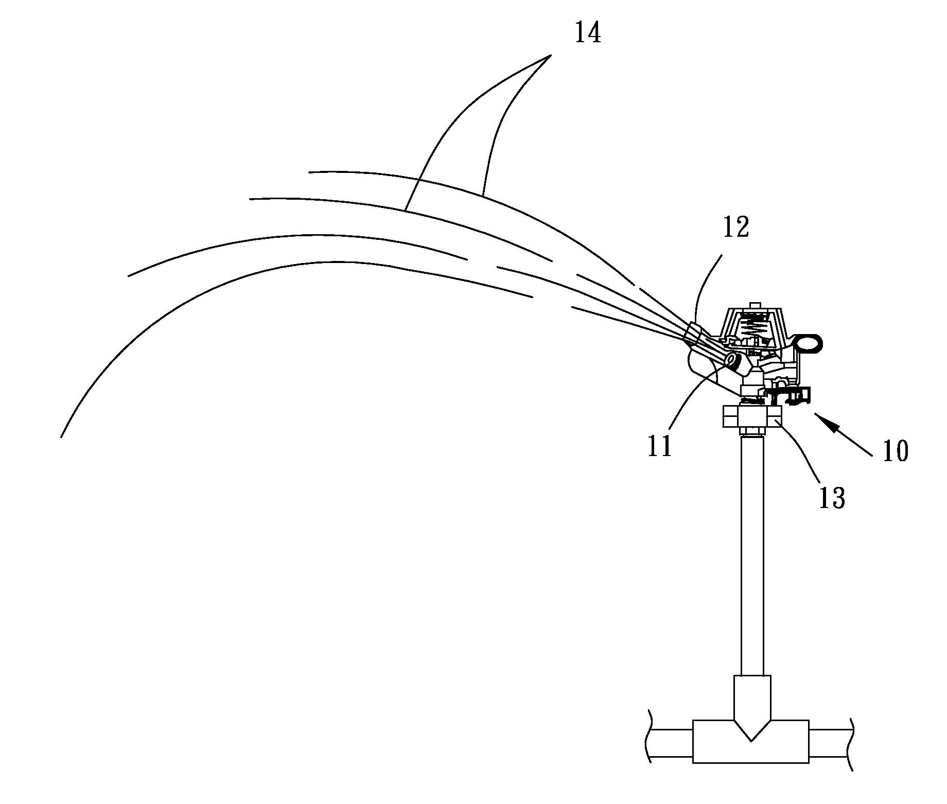
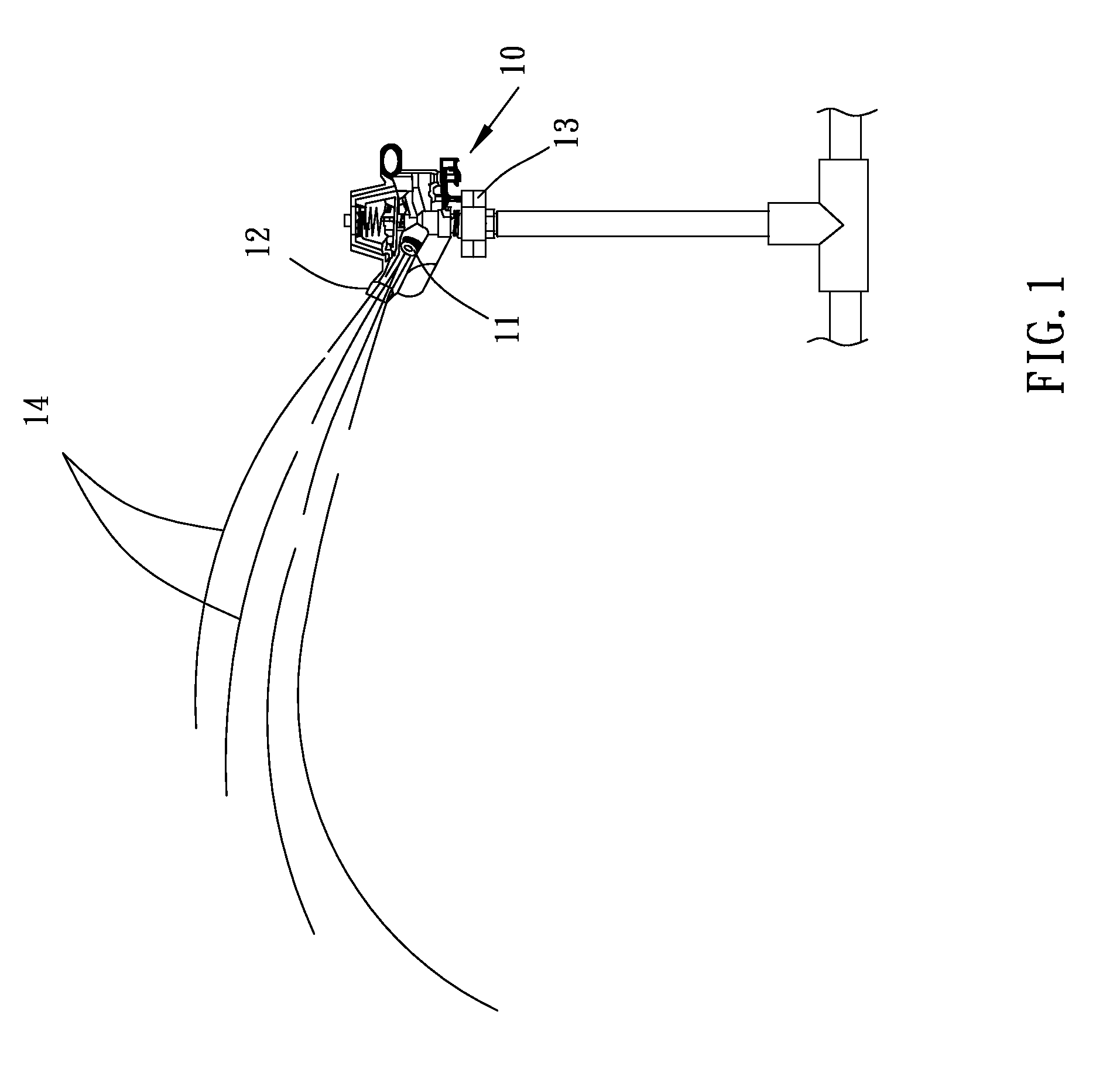
However, the abovementioned conventional sprinkler 1 is widely used and a drawback is discovered from experience.
Therefore the spraying is done unevenly.
Even though the conventional sprinkler and suchlike ones have a structure for adjusting the elevation of spraying, it is not so helpful for improving the drawback of uneven spraying.
Furthermore, dozens or even hundreds of sprinklers are required for large sized farmlands, greenswards or vegetable gardens; it is very troublesome, non-effective and time-wasting for users to employ manpower to adjust the angle of the sprinkler.

Method used


Image

  • Sprinkler Structure
  • Sprinkler Structure
  • Sprinkler Structure

Examples


Embodiment Construction

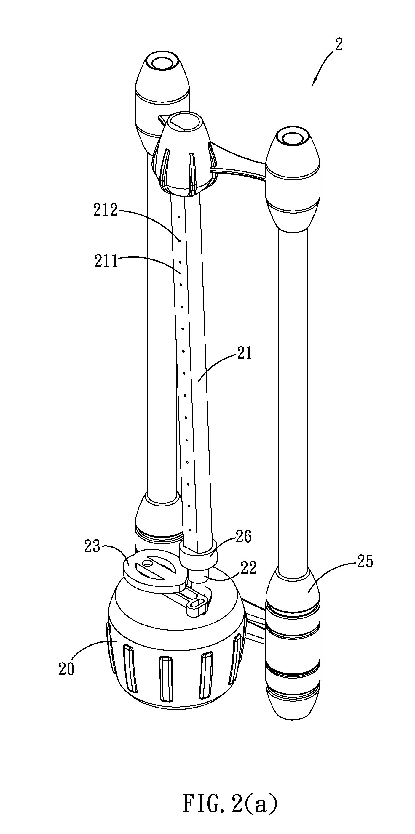
[0022]Referring to FIGS. 2(a), 2(b) and 2(c), they show a preferred embodiment of a sprinkler structure 2 of the present invention which is developed to improve the drawbacks of conventional techniques and means. It is clearly shown in the drawings that, a sprinkler structure 2 of the present invention mainly comprises a shell base 20, a water nozzle 21, a water conveyance element 22, an eccentric gear device 23, a drive gear device 24, a fixing base 25 and a spray angle adjusting element 26. The shell base 20 has a water inlet hole 201 for supplying water current. The water nozzle 21 has a water outlet surface 211, a plurality of spiracles 212 is disposed on the water outlet surface 211 for spraying water. The water conveyance element 22 which is disposed on the shell base 20 and is connected to the water nozzle 21, and the water conveyance element 22 conveys the water current from the water inlet hole 201 to the water nozzle 21.

[0023]The spray angle adjusting element 26 is fixed o...


PUM


Abstract

A sprinkler structure includes a shell base, a water nozzle, a plurality of spiracles, a water conveyance element, an eccentric gear device, a drive gear device, and a fixing base. The eccentric gear device performs an eccentric movement in responding to an external force, and drives the water conveyance element to perform a reciprocating pivotal turning action. The drive gear device is disposed inside the shell base and is coupled to the eccentric gear device. The drive gear device is driven by the water current to rotate, so that the eccentric gear device drives the water conveyance element to perform the reciprocating pivotal turning action. The water nozzle is driven by the reciprocating pivotal turning action to change the angle of the water outlet surface continuously within an angle range. The fixing base is connected to the water nozzle and the shell base.

Description

BACKGROUND[0001]1. Field of Invention[0002]The present invention relates to a sprinkler structure and more particularly to a sprinkler structure which has an eccentric gear device and a drive gear device to drive a water nozzle to change the direction of spraying.[0003]2. Related Art[0004]In order to create beautiful visual effects and a feeling of comfort and spacious, many suburban scenic spots, areas in front of office buildings or residential courtyards have greenswards planted to obtain the abovementioned effects. Presently, most greenswards are transplanted so that the roots are not deeply planted in the soil to absorb water; therefore they have to be sprayed with water regularly. Furthermore, besides the aforementioned greenswards; farmlands and crops grown in gardens also need to be watered regularly in order to grow smoother and faster for harvesting.[0005]For small sized farmlands, greenswards and vegetable gardens, manpower is adequate to take care of watering. But sprink...

Claims


Application Information

Patent Timeline
Patent Type & Authority Applications(United States)
IPC IPC(8): B05B3/00
CPCB05B1/20B05B3/0463B05B3/0445B05B3/044
Inventor HUNG, CHEN-FU
Owner RUEY RYH ENTERPRISE
Learn More