Attachment for tire mounting machine

a tire mounting machine and tire mounting technology, which is applied in the field of tire mounting machines, can solve the problems of limited range, inability to accommodate smaller tires and rims, and standard machines can only be adjusted to handle a minimum rim diameter of six inches, so as to reduce the amount of time to remove tires

Inactive Publication Date: 2013-03-28
BERTRAND TONY
View PDF2 Cites 4 Cited by
  • Summary
  • Abstract
  • Description
  • Claims
  • Application Information

AI Technical Summary

Benefits of technology

The present invention provides a method and apparatus for securing a tire with a small rim to a tire-mounting machine using a plurality of clamp attachments. The invention reduces the time to remove a tire from a small rim using a tire-mounting machine and includes a one-piece body operatively attached to at least one of the plural clamping members having a rim-engaging interface. The machine has a tabletop for receiving the tire and a plurality of clamping members mounted on the table for securing the tire. The clamping attachments are used to secure the tire to the clamping members on the table.

Problems solved by technology

However, the range is limited and generally do not accommodate smaller tires and rims.
For example, standard machines can only be adjusted to handle a minimum rim diameter of six inches.
Therefore, the standard machines are not able secure the tire and rims, nor are they able to remove the tires from the rims.
However, this method is both difficult and time consuming.
Because physical force is used, there is also the possibility that the rim could be damaged.
The addition may be a circular plate, which is heavy, difficult to attach to the table top, and difficult to store due to the size and weight of the plate.
Again, the covers are bulky and are difficult to store.
In addition, the clamp covers are limited as to the type of tire mounting machines that they can work with, and to the rim diameter that they are able to work with.

Method used


Image

  • Attachment for tire mounting machine
  • Attachment for tire mounting machine
  • Attachment for tire mounting machine

Examples


Embodiment Construction

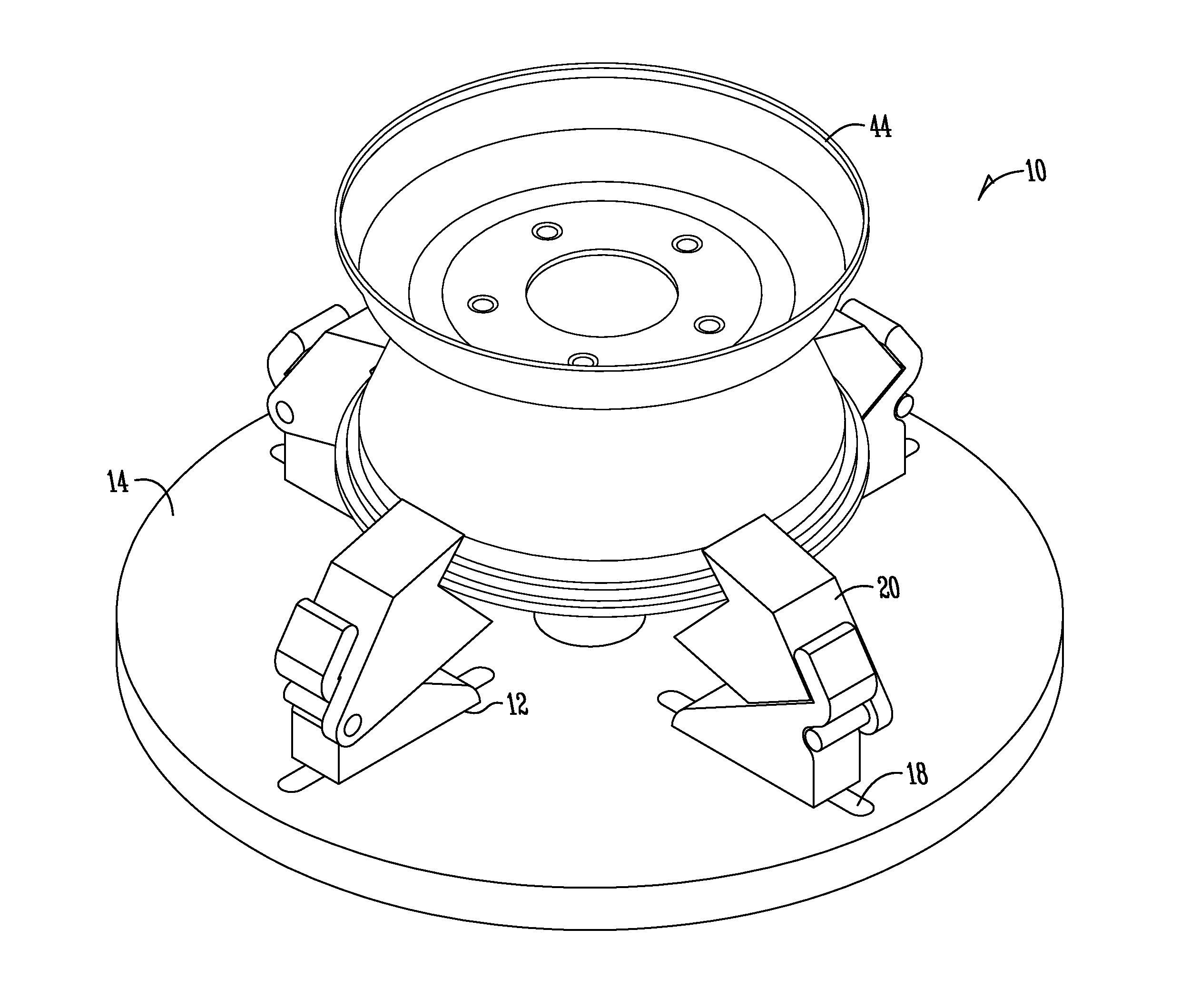
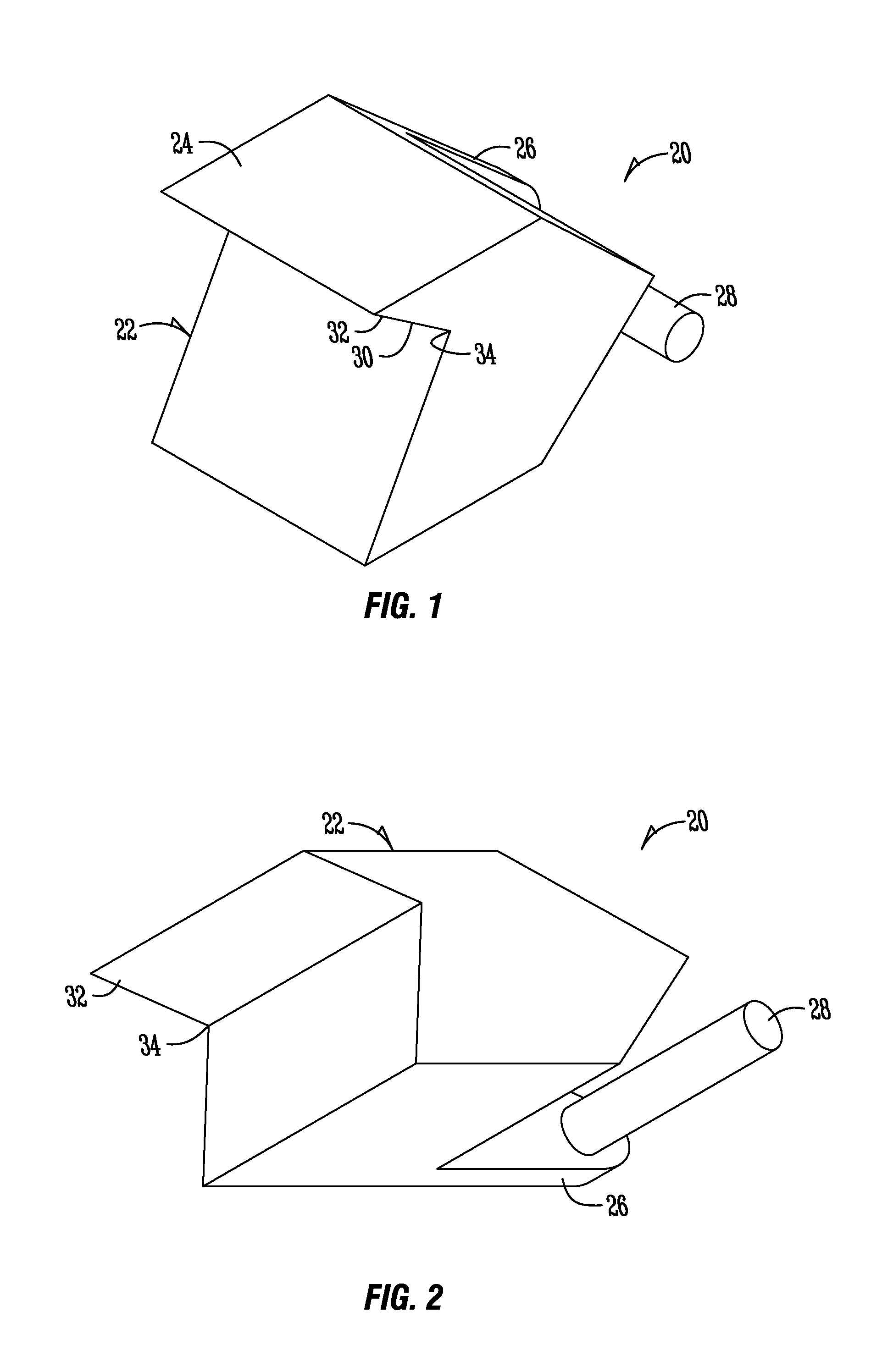
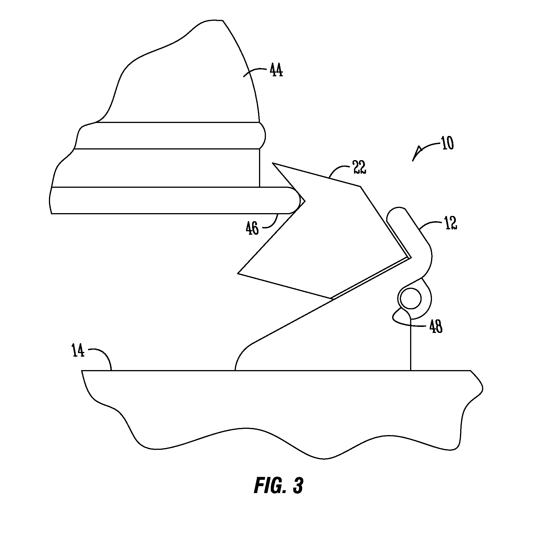
[0026]FIGS. 1 and 2 are perspective views of a clamping attachment 20 for use with a tire-mounting machine 10. The clamping attachment 20 is made from a one-piece body, which includes a first portion 24, a second portion 26, and a third portion 28. In the embodiments shown in FIGS. 1 and 2, the clamping attachment comprises cast aluminum. The present invention also contemplates that the clamping attachment 20 is milled or otherwise machined from a piece of aluminum. However, the three portions may also be individually manufactured, cast, molded, or machined, and welded or otherwise attached to one another. In addition, other materials, such as steel or the like, may be used to construct the attachment. The first portion 24 of the clamping attachment 20 includes a rim-engaging interface 30 for clamping a rim 44 of a tire 42 to a tire-mounting machine 10 such that a tire 42 may be either removed from or added to the rim. The first portion 24 may also include a lip 32 and a recess 34 t...


PUM

PropertyMeasurementUnit
Forceaaaaaaaaaa
Diameteraaaaaaaaaa

Abstract

A clamping attachment for assisting in securing a small tire rim to a tire-mounting machine having a plurality of clamping members is provided. The clamping attaching includes a first portion having a lip and a recess for providing clamping forces to a tire rim. The attachment also includes second and third portions for aiding in attaching the attachment to existing clamping members of a tire-mounting machine. The clamping attachments are used with tires having smaller diameters than what the tire-mounting machines are capable of securing to the tabletop under normal operating conditions. The attachments are configured to be quickly added to the machines to provide for securing the rims to the machine in order to add or remove a tire from the rim.

Description

CROSS-REFERENCE TO RELATED APPLICATIONS[0001]This application claims priority under 35 U.S.C. §119 to provisional application Ser. No. 61 / 384,225 filed Sep. 28, 2010, herein incorporated by reference in its entirety.FIELD OF THE INVENTION[0002]The present invention relates generally to an improved tire-mounting machine for replacing a tire on a rim. More particularly, but not exclusively, the invention relates to a clamping attachments for securing small tires to tire mounting machines.BACKGROUND OF THE INVENTION[0003]Tire mounting machines have been known and used for many years. The machines aid in the process of removing a tire from a rim, and also in replacing the tire with a new one to the same rim. The tire-mounting machine improves efficiency in replacing the tires, which increases the productivity of tire shops, garages, dealerships, and other automobile businesses in being able to change tires for a customer's vehicle rather quickly and with minimal physical work.[0004]Most...

Claims


Application Information

Patent Timeline
IPC IPC(8): B60C25/132B23P17/00B60C25/00
CPCY10T29/49998B60C25/0539
Inventor BERTRAND, TONY
Owner BERTRAND TONY
Why Eureka
Try Eureka