
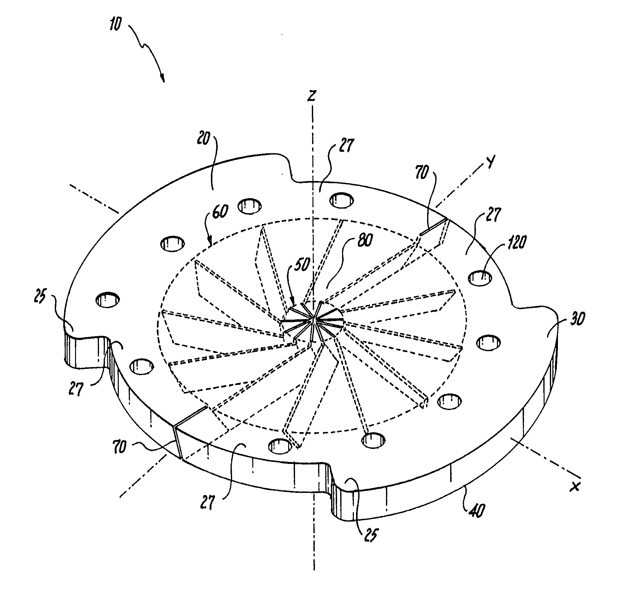
Large french size hemostatic valve configuration

a technology of hemostatic valve and large size, which is applied in the field of hemostasis valve, can solve the problems of difficult introduction of lead, significant blood loss of patients, embolism in the vascular system of patients, etc., and achieve the effect of facilitating sealing the passag

Active Publication Date: 2013-03-21
OSCOR
View PDF1 Cites 8 Cited by
  • Summary
  • Abstract
  • Description
  • Claims
  • Application Information

AI Technical Summary

Benefits of technology

The patent describes a valve for a vascular introducer that helps stop bleeding. The valve has a seal region with two groups of linear cuts. The first group of cuts allows for the sealed passage of medical devices through the seal region. The second group of cuts allows for a wider range of medical device sizes to be sealed passed through the valve. The technical effect of this design is to provide a reliable and flexible way to stop bleeding during medical procedures.

Problems solved by technology

Once the sheath has been inserted into a blood vessel, it provides a passage for the free flow of blood, which may result in significant blood loss from a patient.
The sheath also provides an open passage for the introduction of air into the blood vessel, which may cause an embolism in the vascular system of the patient.
This makes introduction of a lead difficult and can actually cause damage to the lead.
The prior art hemostasis valve designs are not capable of providing an effective hemostatic seal on introduced medical devices having a very wide range of French sizes, and are especially challenged when presented with larger French size devices (e.g. larger than 12F), because such designs use radially aligned slits that form triangular gaps at the slit intersections, which leak blood and / or fluid upon insertion of a medical device.
Additionally, such prior art hemostasis valve designs are not capable of sealing a wide variety of French sizes, while still maintaining the ability to break and peel away after use.
Such combinatorial medical device units pose a challenge that exceeds the capabilities of prior art hemostasis valve designs.
Additionally, such prior art hemostasis valve designs are not able to provide effective hemostatic seals when more than one medical device is introduced through the hemostasis valve simultaneously.

Method used


Image

  • Large french size hemostatic valve configuration
  • Large french size hemostatic valve configuration
  • Large french size hemostatic valve configuration

Examples


Embodiment Construction

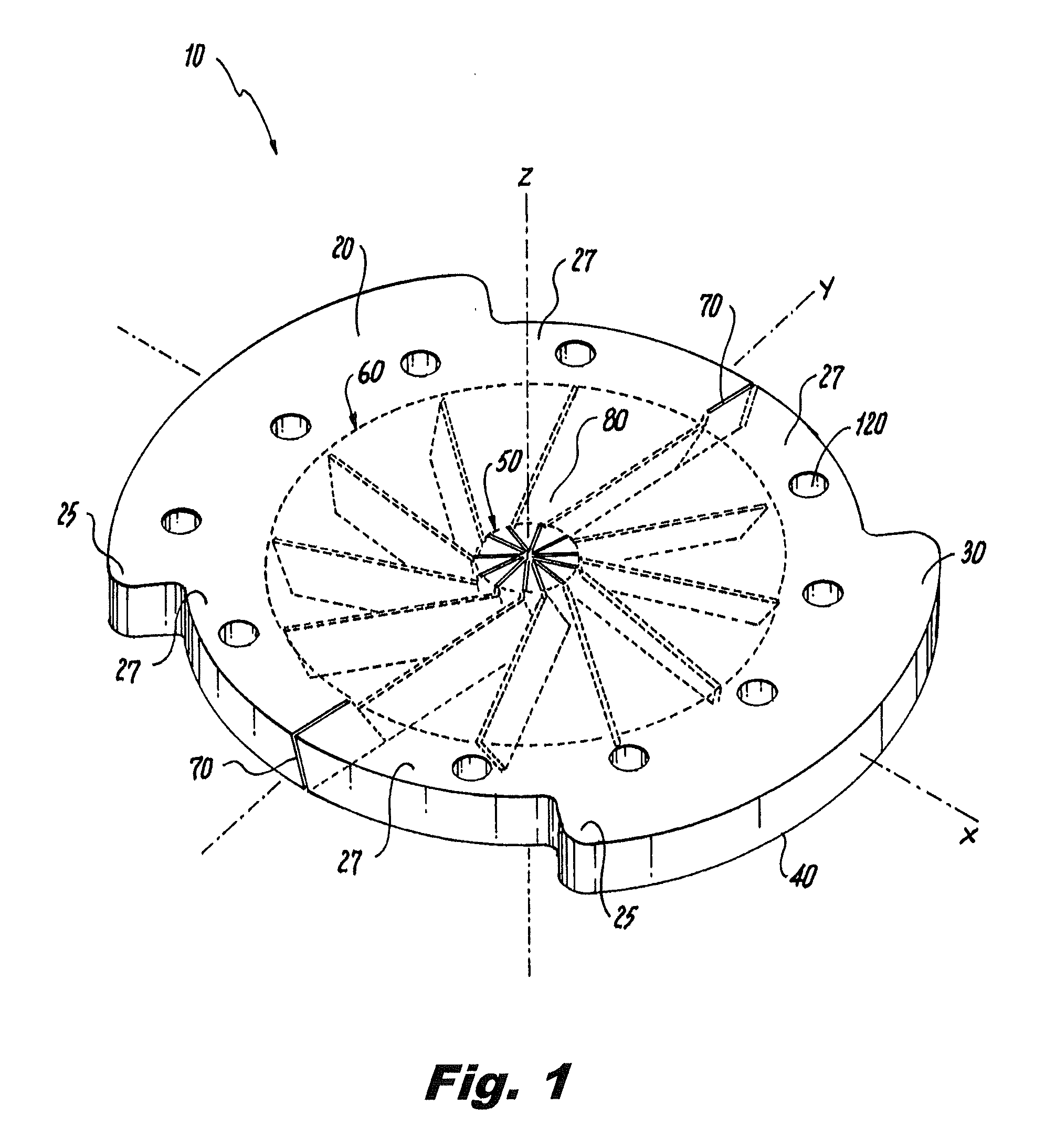
[0030]Referring now to the drawings wherein like reference numerals identify similar structural features or aspects of the medical devices disclosed herein, there is illustrated in FIG. 1 an exemplary embodiment of a novel hemostasis valve member of the invention designated generally by reference numeral 10.

[0031]An exemplary vascular introducer is disclosed in U.S. Patent Application Publications 2008 / 0097386 and 2010 / 0312190, both of which are incorporated herein by reference in their entirety for purposes of enablement and illustration. Those skilled in the art will readily appreciate that the disclosure of vascular introducer 10 should not be construed as limiting the scope of the subject invention in any way. In other words, while the hemostasis valve of the subject invention can certainly be employed with the exemplary vascular introducer of, for example, U.S. Patent Application Publication 2010 / 0312190, it can also be employed with other types of vascular introducers, includi...


PUM


Abstract

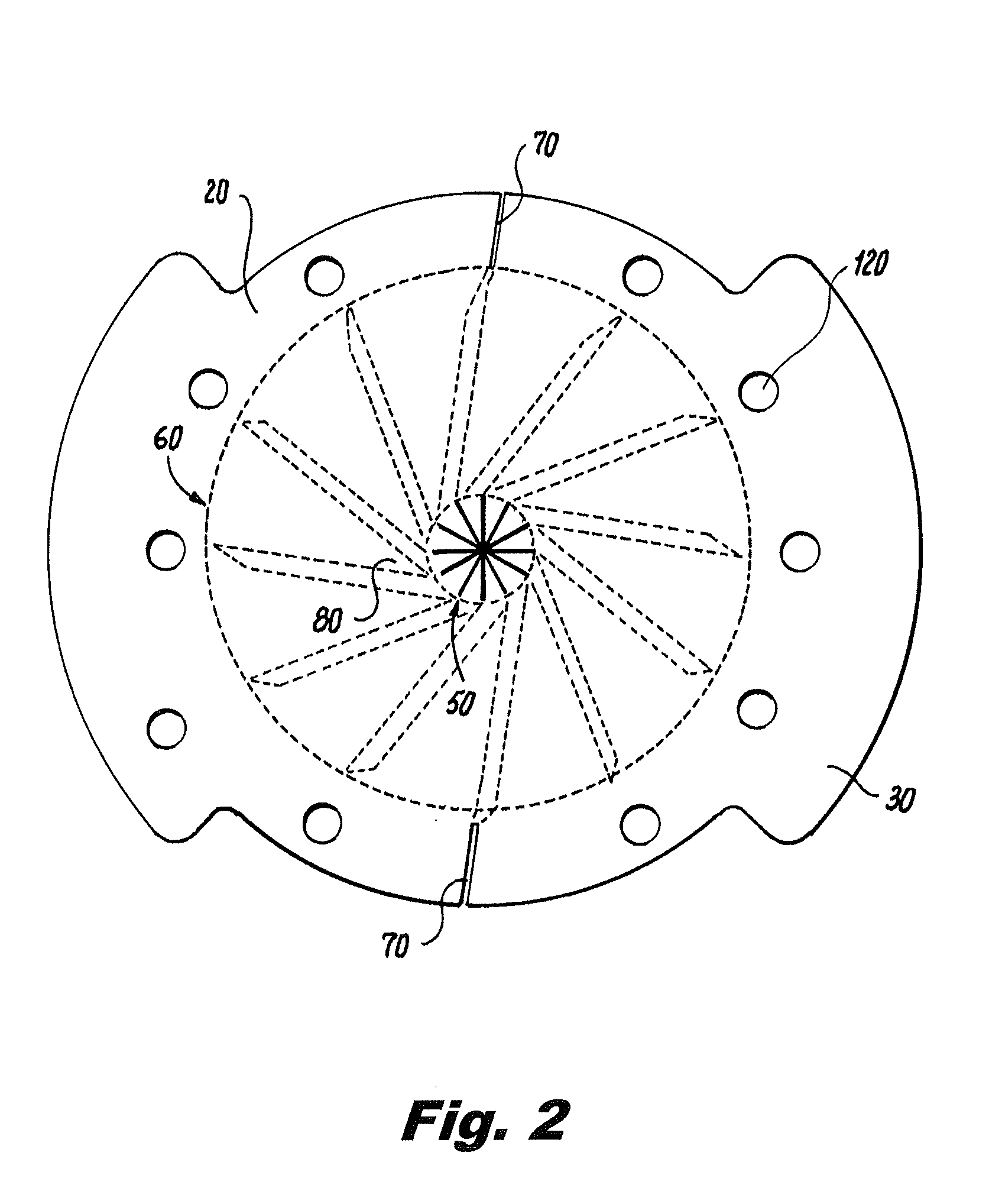
A hemostasis valve for a vascular introducer includes a valve body having a seal region with opposed substantially planar proximal and distal end surfaces and a central axis extending through the seal region perpendicular to the proximal and distal end surfaces. The seal region has a first grouping of circumferentially arranged and equidistantly spaced linear cuts extending radially outward from the central axis, and through the seal region from the proximal end surface to the distal end surface. The seal region has a second grouping of circumferentially arranged and equidistantly spaced linear cuts in the distal end surface extending tangentially outward from the first grouping of linear cuts, and partially from the distal end surface to a depth short of the proximal end surface to facilitate passage of a variety of sizes of medical devices through the seal region.

Description

CROSS-REFERENCE TO RELATED APPLICATIONS[0001]This application claims the benefit of priority to U.S. Provisional Patent Application No. 61 / 535,485, filed Sep. 16, 2011, which is incorporated by reference herein in its entirety.BACKGROUND OF THE INVENTION[0002]1. Field of the Invention[0003]The subject invention is directed to a hemostasis valve for vascular introducers that provides a complete hemostatic seal regardless of the diameter of the object introduced through the valve, while exhibiting lower insertion and extraction forces than prior-art hemostasis valves.[0004]2. Description of Related Art[0005]The percutaneous introduction of diagnostic and therapeutic devices such as pacemaker leads and cardiovascular catheters into a blood vessel is typically accomplished with the aid of an introducer assembly. Introducer assemblies generally include a dilator having a tapered end portion and a thin-walled introducer sheath having a lumen extending through the sheath to initially accom...

Claims


Application Information

Patent Timeline
IPC IPC(8): A61M29/00
CPCA61M39/0606Y10T137/7885
Inventor SEARFOSS, TIMOTHY A.OSYPKA, THOMAS P.
Owner OSCOR
Learn More