
Upright support configuration for a pallet racking system

a pallet racking and support configuration technology, applied in the direction of storage devices, cabinets, show hangers, etc., can solve the problems of lack of strength, high cost of heavy duty steel beams in pallet racking, and inconvenient use of heavy duty steel beams

Inactive Publication Date: 2013-03-21
GLIDESTORE FREETRACK PTY LTD
View PDF8 Cites 12 Cited by
  • Summary
  • Abstract
  • Description
  • Claims
  • Application Information

AI Technical Summary

Benefits of technology

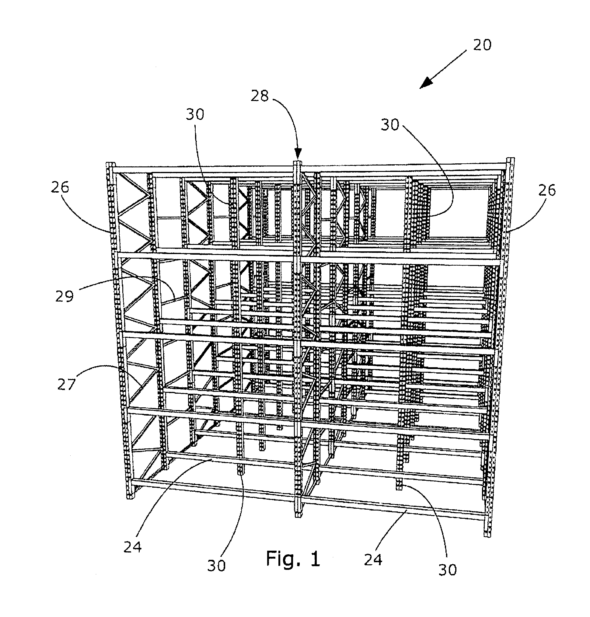
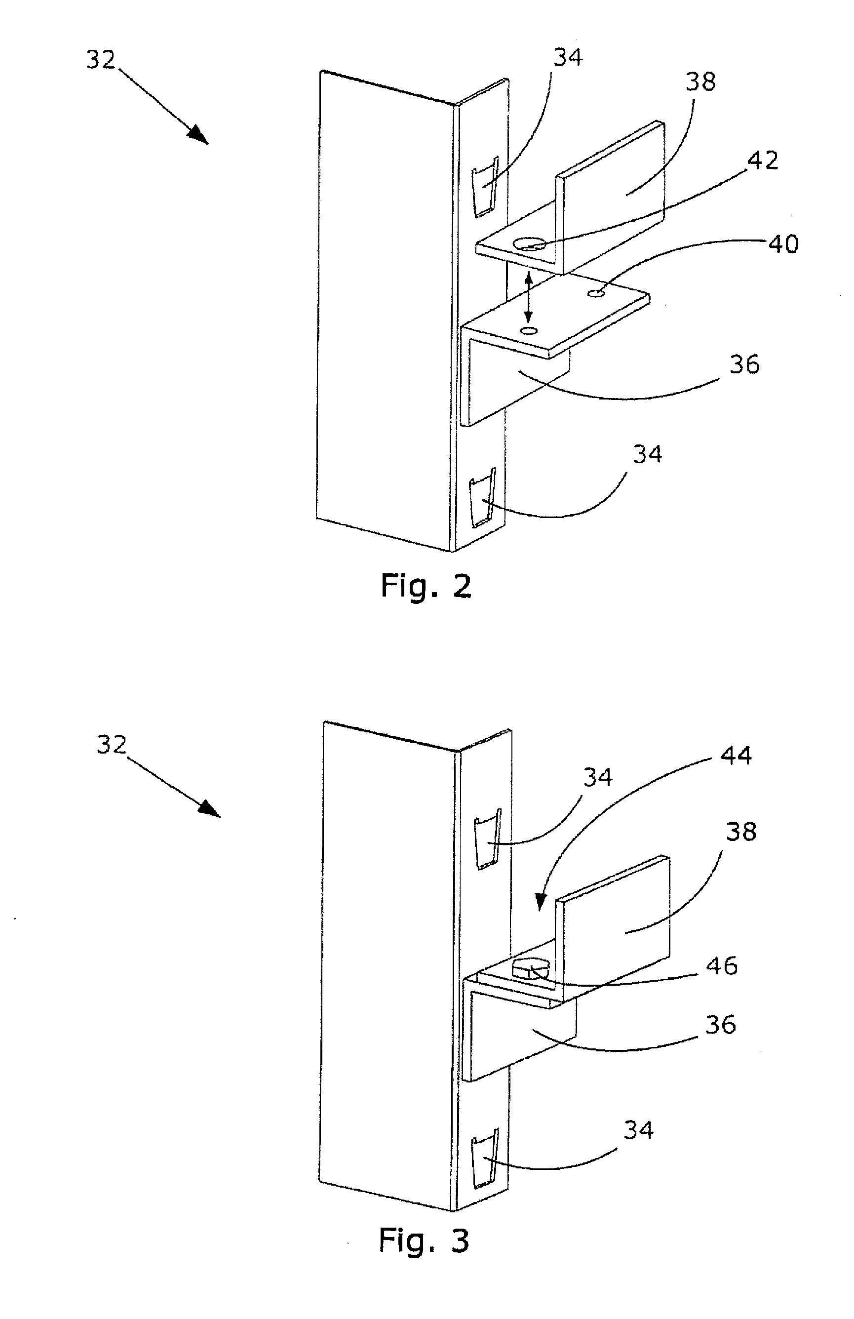
The patent describes a way to reinforce a cross beam in a pallet racking system without adding a new frame or sacrificing its length. An additional upright support and bracket are placed between the existing frame assemblies to support the cross beam with two pallets on its sides. The bracket also prevents the cross beam from moving along its depth dimension. This solution can be used in various structural systems, not just pallet racking.

Problems solved by technology

The disadvantage of this system, however, is that it is labour intensive given the care the forklift driver must take driving in and out of the racking, and is thus is also time consuming.
Another disadvantage is the repair costs which are involved when errors or accidents occur with the forklifts.
The beams are commonly therefore made from steel or other similarly sturdy material, however use of heavy duty steel beams in pallet racking is cost prohibitive.
Cross beams made from cheaper and lighter material or beams of a lower cross-sectional amount of steel can be used and are desirable, however, the lack of strength in these beams can lead the centre of the beam to depress, distort or rotate under the pressure of the pallet weight and movement.
The beam is therefore structurally weak and dangerous and cannot accommodate the desired weight of the pallets.

Method used


Image

  • Upright support configuration for a pallet racking system
  • Upright support configuration for a pallet racking system
  • Upright support configuration for a pallet racking system

Examples


Embodiment Construction

[0071]The following detailed description of the invention refers to the accompanying drawings. Wherever possible, the same reference numbers will be used throughout the drawings and the following description to refer to the same and like parts. Dimensions of certain parts shown in the drawings may have been modified and / or exaggerated for the purposes of clarity or illustration.

[0072]The present invention relates to a pallet racking system and bracket therefor which allows for horizontal cross beams supporting the pallets to be constructed of cheaper and lighter material and / or be of lesser cross sectional size than hitherto known beams used in conventional pallet racking systems. The present invention can be used in conjunction with either the “Pushback” or “Flowthrough” racking systems which are known, but it is to be understood that the invention could equally well be applied to any kind of racking system.

[0073]Referring now to the drawings there is illustrated in FIG. 1 a rackin...


PUM


Abstract

The present invention relates to an upright reinforcing assembly for use with a pallet racking system, and racking system incorporating the same. The support configuration consists of an upright support and attached a bracket containing two L-shaped platforms which form a pocket. The upright support configuration is placed between two frame assemblies to support the beam, which is held in the pocket created by the bracket, thereby providing additional support to the beam and preventing rotation, bowing or distortion of the beam. Such a configuration lowers the cost of pallet racking as lower capacity beams can be used, or otherwise less frame assemblies are required in the racking.

Description

FIELD OF THE INVENTION[0001]The present invention relates to a pallet racking system and reinforcing assembly therefor. In particular, the invention relates to a system that includes intermediate supports consisting of an upright support and a bracket with a base support and upright component which, when assembled, provide support to a pallet racking beam.BACKGROUND TO THE INVENTION[0002]Pallet storage systems used to store cargo-carrying pallets are known. Such systems typically include a support frame for supporting the pallets and which are loadable from one or more ends of the frame. These frames are generally designed in a grid formation including upright frame assemblies and connected by beams or shelves creating levels upon which the pallets are loaded by a forklift. Typically 2 or more pallets can be accommodated between each frame assembly.[0003]A common and known racking system is the ‘Drive-in’ system wherein the forklift is driven in between the lanes or bays of the syst...

Claims


Application Information

Patent Timeline
IPC IPC(8): A47B55/00A47B96/00
CPCA47B53/00B65G1/02A47B57/402
Inventor PARKER, BRIAN
Owner GLIDESTORE FREETRACK PTY LTD
Learn More