
Centrifugal Magnetic Heating Device

a magnetic heating and centrifugal technology, applied in the direction of lighting and heating apparatus, solar radiation reduction, etc., can solve the problems of wind turbine power generation system that cannot be seen in a large-scale power supply facility, inability to accept the output power limit, and large number of expensive electronic devices, etc., to achieve the effect of reducing cost, simplifying wiring structure and reducing spacing

Inactive Publication Date: 2013-03-14
HSU WAN CHUN
View PDF3 Cites 34 Cited by
  • Summary
  • Abstract
  • Description
  • Claims
  • Application Information

AI Technical Summary

Benefits of technology

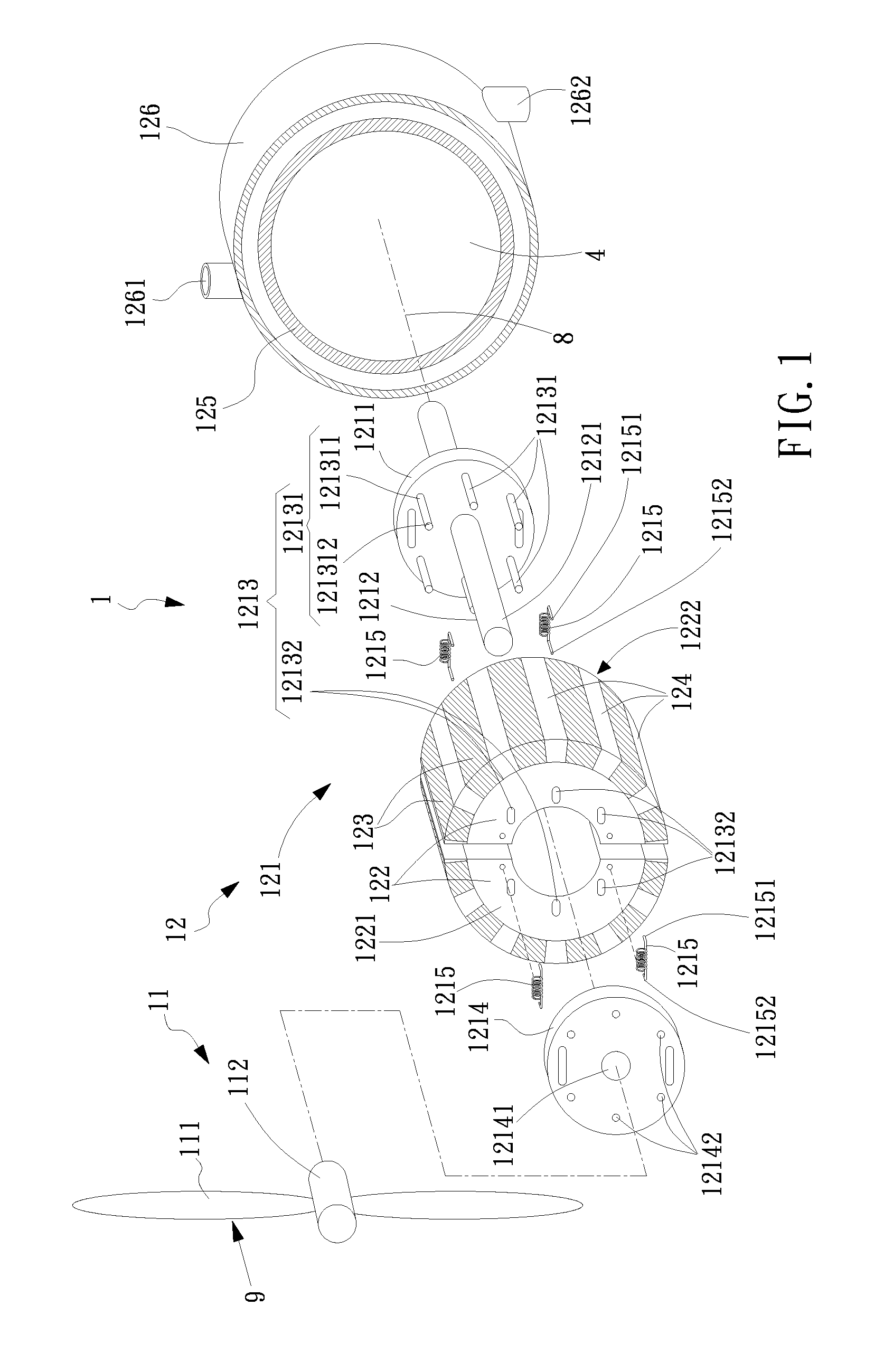
The present invention is a centrifugal magnetic heating device that uses wind power to generate heat without the need for complicated wiring and circuitry. It includes a power receiving mechanism with a vane set and transmission module and a heat generator with a centrifugal mechanism and magnets. The device automatically adjusts the magnetic field to induce eddy currents and generate heat through the rotation of the magnets. The technical effect is to reduce costs and complexity in generating heat while maintaining efficient heat generation.

Problems solved by technology

Currently, the wind turbine power generation system needs a large number of expensive electronic devices and also has an inacceptable limit in output power.
Thus, the wind turbine power generation system can only be seen in a large-scale power supply facilities, and is definitely not popular to ordinary consumers.
One of the shortcomings in the solar energy system, either a parallel power regeneration system or a direct heating system, is the cost for the energy.
Yet, such a system is highly climate-independent.
In the cold winter, poor sunshine usually reduces the collection in solar energy, and as a consequence an auxiliary heating system is required for the dark night usage.
Also, obvious disadvantages of the solar system are its space occupation and again the cost.

Method used


Image

  • Centrifugal Magnetic Heating Device
  • Centrifugal Magnetic Heating Device
  • Centrifugal Magnetic Heating Device

Examples


third embodiment

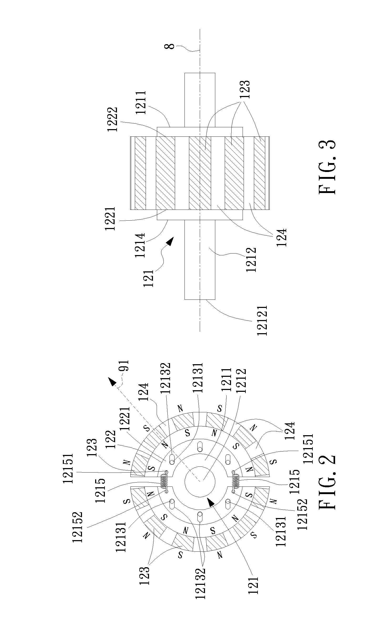
[0063]Referring now to FIG. 9, FIG. 10 and FIG. 11, a first, a second and arrangements of the permanent magnets for the centrifugal magnetic heating device in accordance with the present invention are shown, respectively. In the present invention, the arrangement of the permanent magnets 123 on the bases 122 can be an arrangement of having plural sets (two shown in FIG. 9) of permanent magnets 123a to surround exteriorly the bases 122 along the center axial direction 8 in a symmetric, horizontal and parallel manner (as shown in FIG. 9), an arrangement of having a helix set of the permanent magnets 123b to surround exteriorly the bases 122 along the center axial direction 8 in a twist manner by compared to FIG. 9 (as shown in FIG. 10), or an arrangement of having plural sets (two shown in FIG. 11) to surround exteriorly the bases 122 along the center axial direction 8 in an asymmetric and helix manner like FIG. 10 (as shown in FIG. 11).

[0064]Referring now to FIG. 12, an exploded view...

second embodiment

[0070]Referring now to FIG. 16 and FIG. 17, cross-sectional views of a first and the heat generator for the centrifugal magnetic heating device in accordance with the present invention are shown, respectively. The heat generator 12 for the centrifugal magnetic heating device 1 in accordance with the present invention can be installed on a platform 5 as shown in FIG. 16, while the heat generator 12 can be any of FIG. 13, FIG. 14 and FIG. 15. As illustrated in FIG. 16, the heat generator 12 is the same as that shown in FIG. 13.

[0071]Furthermore, as shown in FIG. 17, the heat generator 12 can be installed into a housing or a frame 6. The transmission shaft 1212 of the centrifugal mechanism 121 is hold in between by a pair of bearings 3 on the housing 6, one located above the heat generator 12 and another located below the heat generator 125. The heat generator 12 can be any of FIG. 13, FIG. 14 and FIG. 15. In particular, with the conductive member 125 to be mounted fixedly inside the h...

first embodiment

[0075]In the centrifugal magnetic heating device in accordance with the present invention 1a, the heat generator 12 can also adopt any of the designs shown in FIG. 1(12), FIG. 12(12a), FIG. 13(12b), FIG. 14(12c) and FIG. 15(12d).

[0076]Referring now to FIG. 19, a second embodiment of the centrifugal magnetic heating device in accordance with the present invention is shown. It is noted that the major difference between this embodiment and that shown in FIG. 18 is that the power receiving mechanism 11b of this embodiment 1b is a horizontal-shafting type.

[0077]Referring now to FIG. 20, a third embodiment of the centrifugal magnetic heating device in accordance with the present invention is shown. It is noted that the major difference between this embodiment and that shown in FIG. 18 is that in this embodiment 1b the heat storing apparatus 13 and the heat generator 12 are directly connected in a fluid communication manner. In this arrangement, an input junction 131 and an output junction...


PUM


Abstract

A centrifugal magnetic heating device includes a power receiving mechanism and a heat generator. The power receiving mechanism further includes a vane set and a transmission module. The heat generator connected with the transmission module further includes a centrifugal mechanism connected to the transmission module, a plurality of bases furnished on the centrifugal mechanism, a plurality of magnets furnished on the bases individually, and at least one conductive member corresponding in positions to the magnets. The vane set is driven by nature flows so as to drives the bases synchronically with the magnets through the transmission module, such that the magnets can rotate relative to the conductive member and thereby cause the conductive member to generate heat.

Description

[0001]This application claims the benefit of Taiwan Patent Application Serial No. 100132972, filed on Sep. 14, 2011, the subject matter of which is incorporated herein by reference.BACKGROUND OF INVENTION[0002]1. Field of the Invention[0003]The invention relates to a centrifugal magnetic heating device, and more particularly to the device that utilizes natural flows, such as the wind flow, to drive a power receiving mechanism to further rotate a conductive member in a suspension way inside a centrifugal mechanism and interacting with the stationary magnets of a heat generator for generating heat therefrom.[0004]2. Description of the Prior Art[0005]In the art, the wind turbine power generation system is known to be one of modem environment-friendly power generation systems, which utilizes wind turbines to collect wind power by activating a generator to generate electric energy. Currently, the wind turbine power generation system needs a large number of expensive electronic devices an...

Claims


Application Information

Patent Timeline
Patent Type & Authority Applications(United States)
IPC IPC(8): H05B6/02F24V50/00
CPCH05B6/108H05B6/109F24J3/00Y02E10/72F24H1/00F24H2250/08F03D9/006F03D9/22F24V99/00Y02E60/16Y02E70/30F03D9/007F03D9/17F03D9/28
Inventor HSU, WAN CHUN
Owner HSU WAN CHUN
Learn More