
Cannula tips, tissue attachment rings, and methods of delivering and using the same

a technology of tissue attachment and cannula, which is applied in the field of medical devices and methods, can solve the problems of time-consuming and labor-intensive, and limit the adjustability of the cannula position after it has been secured, and achieve the effect of reducing the risk of infection

Active Publication Date: 2013-03-07
CIRCULITE
View PDF5 Cites 48 Cited by
  • Summary
  • Abstract
  • Description
  • Claims
  • Application Information

AI Technical Summary

Benefits of technology

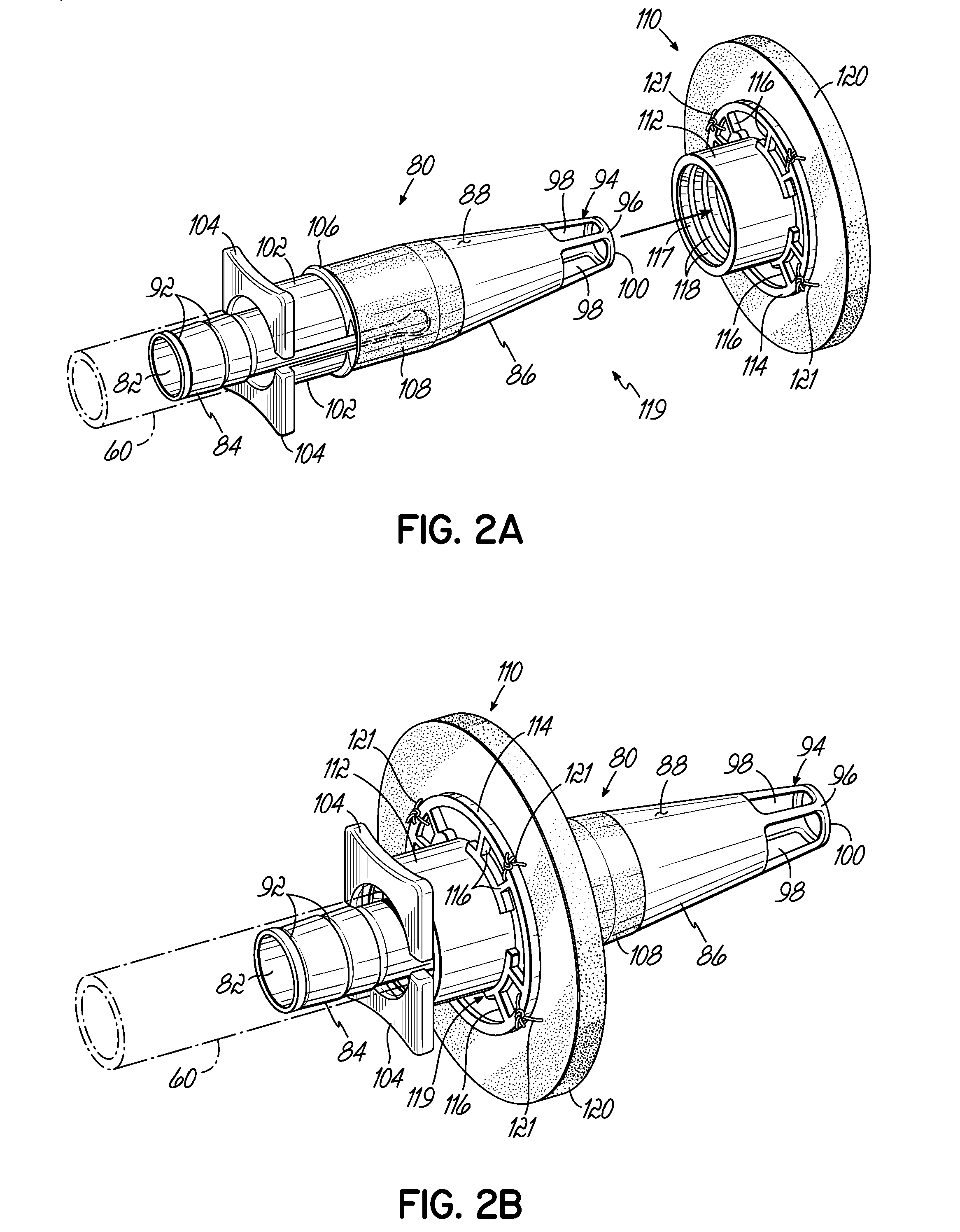
The present invention describes a surgical cannula system with a locking mechanism that can secure the cannula in different positions with respect to a tissue attachment ring. The locking mechanism can transition between a first and second locking state, and can include a first and second locking elements that are operably coupled to the tissue attachment ring and the cannula, respectively. The cannula can be secured in at least two positions, and the first and second positions may define boundary positions, between which the position of the cannula is variable. The cannula delivery system includes a cannula with an expandable portion that can engage an inner surface of the tissue attachment ring to dilate a puncture in the biological tissue. The method of securing a cannula to a surgical site involves attaching a tissue attachment ring to the surgical site and directing the cannula through the lumen of the tissue attachment ring. The locking mechanism is transitioned from the first to second locking state to secure the position of the cannula with respect to the tissue attachment ring.

Problems solved by technology

For instance, blood pumps with inflow and outflow cannulae assist the heart in circulating blood in a patient experiencing congestive heart failure and a transplant organ has either not been located or the patient is not a suitable candidate for the transplant.
However, known conventional cannula designs are often secured to the tissue surrounding the particular cavity by one or more sutures, which limits the adjustability of the cannula position after it has been secured.
Furthermore, when a sewing ring is used in securing the cannula to the tissue, proper placement of the sewing ring relative to the cannula may be time consuming.

Method used


Image

  • Cannula tips, tissue attachment rings, and methods of delivering and using the same
  • Cannula tips, tissue attachment rings, and methods of delivering and using the same
  • Cannula tips, tissue attachment rings, and methods of delivering and using the same

Examples


Embodiment Construction

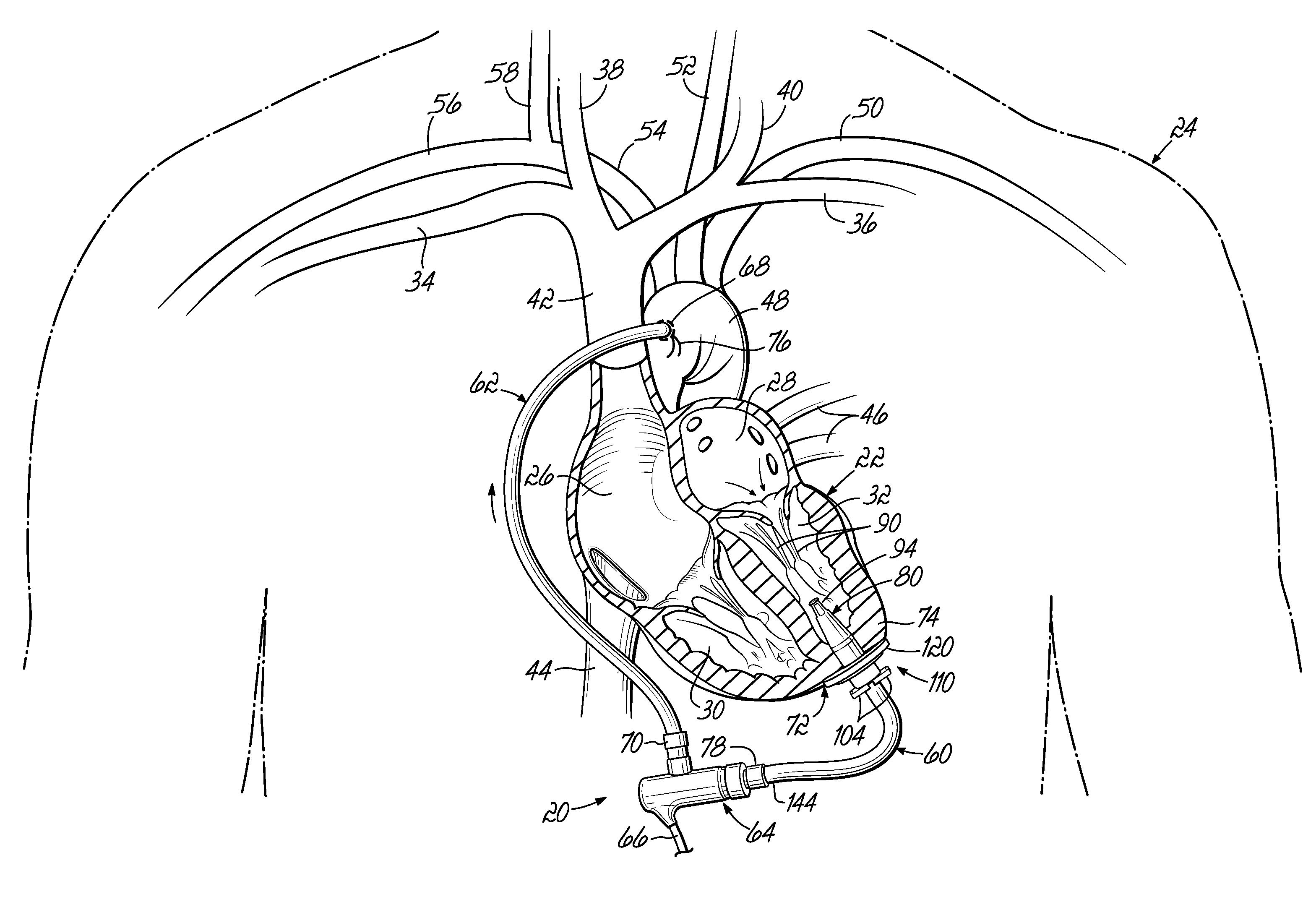
[0041]While the various embodiments of the present invention may be useful for use with any organ or cavity within the body, including, for example, the kidneys, the bladder, the stomach, or the heart, the illustrated examples included herein are drawn specifically to applications with the heart.

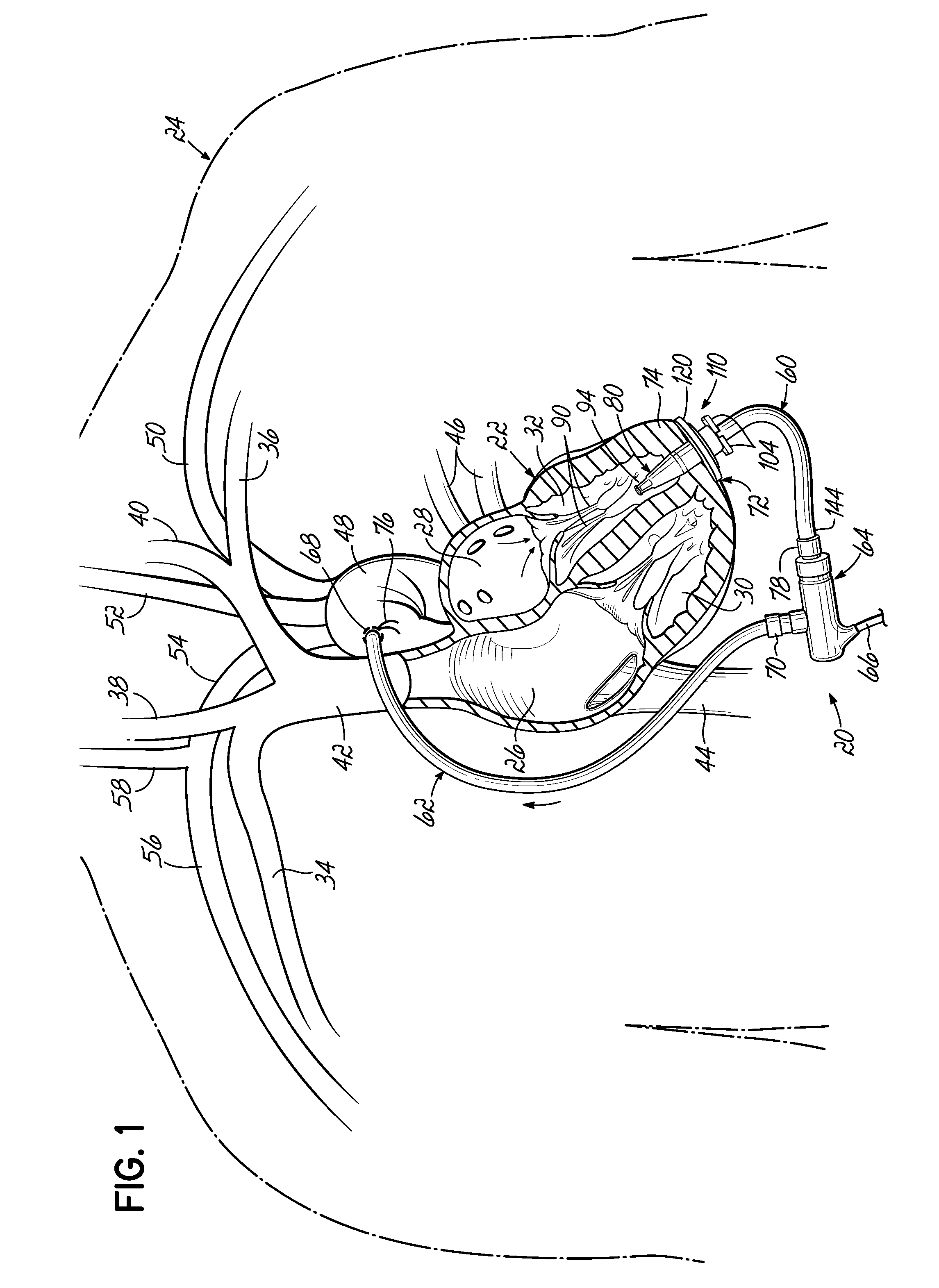
[0042]FIG. 1 illustrates one embodiment of an implanted circulatory assist device 20 implanted in a pediatric patient. For illustrative purposes, certain anatomy is shown including the heart 22 of the patient 24 having a right atrium 26, a left atrium 28, a right ventricle 30, and a left ventricle 32. Blood from the right and left subclavian veins 34, 36 and the right and left jugular veins 38, 40 enters the right atrium 26 through the superior vena cava 42 while blood from the lower parts of the body enters the right atrium 26 through the inferior vena cava 44. The blood is pumped from the right atrium 26, to the right ventricle 30, and to the lungs (not shown) to be oxygenated. Blood retur...


PUM


Abstract

A surgical cannula system. The surgical cannula system includes a cannula having a proximal end, a distal end, and a lumen extending therebetween. A tissue attachment ring, being configured to be coupled to a biological tissue, includes a lumen extending therethrough. A locking mechanism has a first locking state, in which the cannula is configured to move with respect to the tissue attachment ring, and a second locking state, in which movement of the cannula with respect to the tissue attachment ring is resisted.

Description

CROSS-REFERENCE TO RELATED APPLICATION[0001]This application claims the benefit of U.S. Provisional Patent Application Ser. No. 61 / 531,957, filed on Sep. 7, 2011 (pending), the disclosure of which is incorporated by reference herein, in its entirety.FIELD OF THE INVENTION[0002]The present invention relates generally to medical devices and methods for assisting the conduction of bodily fluids and, more particularly, to devices and methods for securing a cannula to an organ for moving fluid therefrom.BACKGROUND OF THE INVENTION[0003]Various devices and methods have been utilized to assist in conducting bodily fluids. For instance, blood pumps with inflow and outflow cannulae assist the heart in circulating blood in a patient experiencing congestive heart failure and a transplant organ has either not been located or the patient is not a suitable candidate for the transplant. Accordingly, the blood pump may be fluidically attached to a pumping chamber of the heart and then located remot...

Claims


Application Information

Patent Timeline
Patent Type & Authority Applications(United States)
IPC IPC(8): A61B17/11
CPCA61B17/11A61B2017/00243A61B17/32A61M1/122A61B2017/1135A61B2017/00252A61M1/1008A61B2017/1107A61M60/857A61M60/148A61M60/104A61M60/863A61M60/88A61M60/237A61M60/178A61M60/226A61M60/221A61M60/861
Inventor FARNAN, ROBERT C.DRUMMOND, ARIELLEBRIGHTBILL, JERRYROBINSON, TIMOTHY WALTERWISDOM, RICHARDO'KEEFE, JONATHANABRAHAM, RICHARDKOSTANSKI, SARAHFRITZ, BRYAN
Owner CIRCULITE
Learn More