
Hydrodynamic bearing assembly and method of manufacturing the same

a technology of bearing assembly and bearing body, which is applied in the direction of sliding contact bearings, instruments, record information storage, etc., can solve the problems of deteriorating driving stability of spindle motors and loss of lubricating fluid, and achieve the effect of preventing oil leakag

Inactive Publication Date: 2013-02-28
SAMSUNG ELECTRO MECHANICS CO LTD
View PDF0 Cites 7 Cited by
  • Summary
  • Abstract
  • Description
  • Claims
  • Application Information

AI Technical Summary

Benefits of technology

The present invention provides a hydrodynamic bearing assembly that minimizes lubricating oil scattering. This is achieved by using a lipophilic coating or an oil repellent material on the surface of the stationary members and / or rotating members to prevent lubricating oil leakage from the oil sealing part. The assembly includes a lubricating oil filled so as to form a liquid-vapor interface between stationary members and rotating members, which results in improved performance and efficiency.

Problems solved by technology

However, when an external impact is applied to the spindle motor in a state in which the spindle motor has been driven and stopped, a phenomenon in which the lubricating fluid forming a lubricating fluid interface is leaked to the outside occurs, to thereby cause loss of the lubricating fluid, thereby deteriorating driving stability of the spindle motor.

Method used


Image

  • Hydrodynamic bearing assembly and method of manufacturing the same
  • Hydrodynamic bearing assembly and method of manufacturing the same
  • Hydrodynamic bearing assembly and method of manufacturing the same

Examples


first embodiment

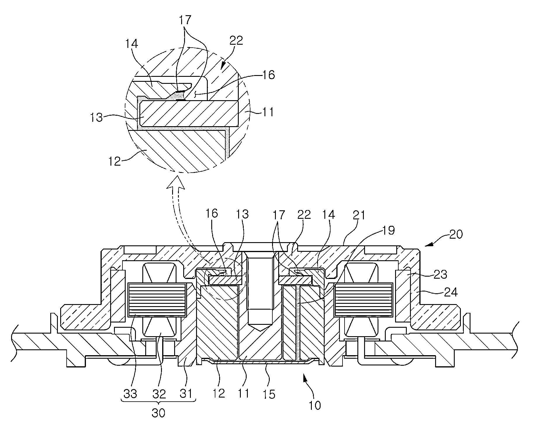
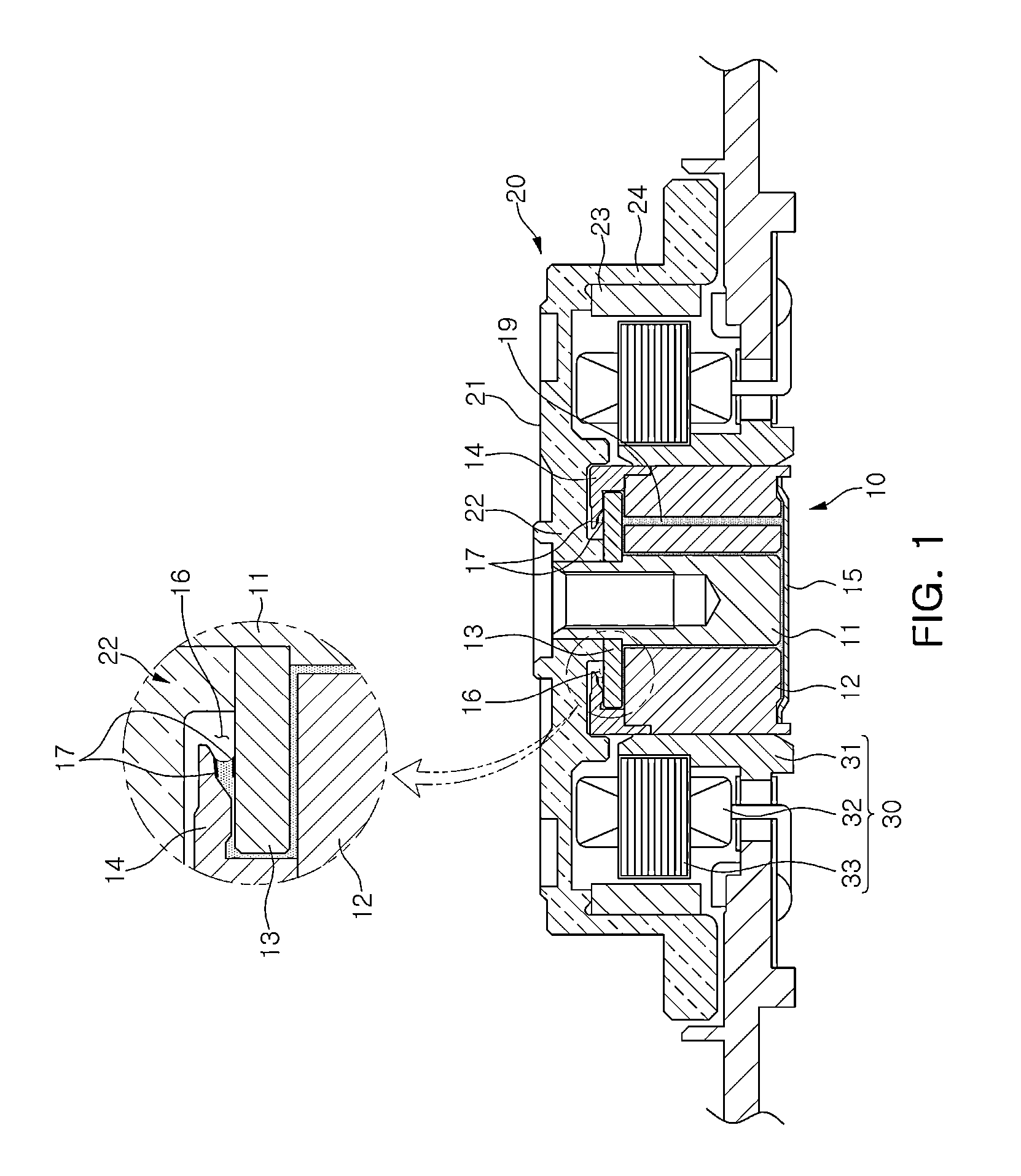
[0035]FIG. 1 is a schematic cross-sectional view of a motor including a hydrodynamic bearing assembly according to the present invention.

second embodiment

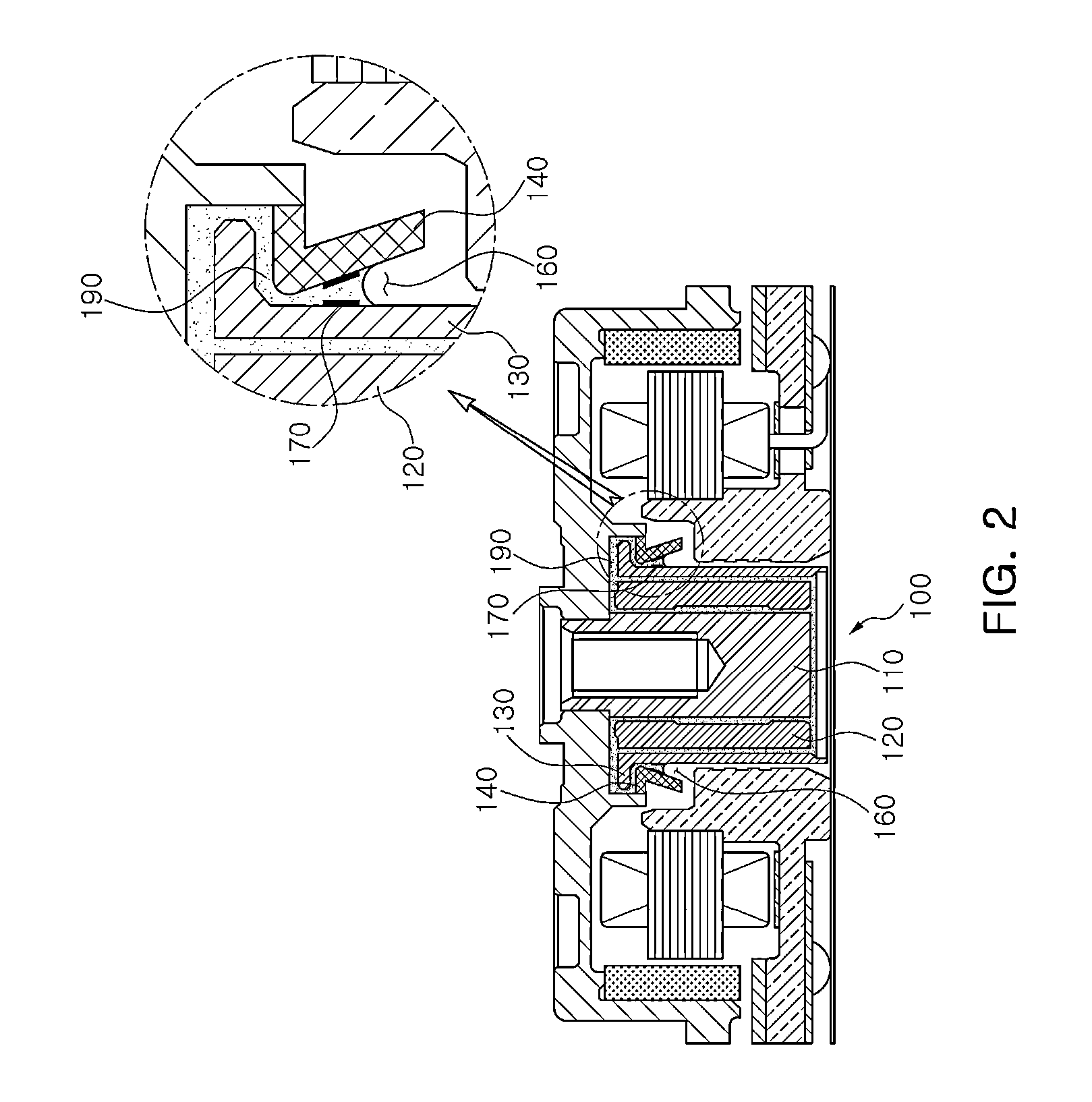
[0036]FIG. 2 is a schematic cross-sectional view of a motor including a hydrodynamic bearing assembly according to the present invention.

third embodiment

[0037]FIG. 3 is a schematic cross-sectional view of a motor including a hydrodynamic bearing assembly according to the present invention.

[0038]Referring to FIG. 1, a hydrodynamic bearing assembly 10 according to the first embodiment of the present invention may include a lubricating oil 19 filled so as to form a liquid-vapor interface between stationary members 12 and 14 and rotating members 11, 13, and 22; and a lipophilic coating 17 formed on the liquid-vapor interface of the lubricating oil 19 so as to prevent leakage of the lubricating oil 19.

[0039]Hereinafter, the above configuration will be described in detail.

[0040]The stationary members may be a sleeve 12 and a cap member 14, and the rotating members may be a shaft 11, a thrust plate 13, and a hub 22.

[0041]An oil sealing part 16 may be formed between the stationary members 12 and 14 and the rotating members 11, 13, and 22, particularly, between the sleeve 12, the thrust plate 13, and the cap member 14.

[0042]The cap member 14...


PUM

PropertyMeasurementUnit
Contact angleaaaaaaaaaa
Lipophilicityaaaaaaaaaa

Abstract

There are provided a hydrodynamic bearing assembly and a method of manufacturing the same. The hydrodynamic bearing assembly includes: a lubricating oil filled so as to form a liquid-vapor interface between stationary members and rotating members; and a lipophilic coating formed on the liquid-vapor interface of the lubricating oil so as to prevent lubricating oil leakage. Therefore, the lipophilic coating is formed on the interface of the lubricating oil and an oil repellent material is formed on a surface of at least one of the stationary members and the rotating members, whereby the scattering and the leakage of the lubricating oil may be effectively prevented.

Description

CROSS-REFERENCE TO RELATED APPLICATIONS[0001]This application claims the priority of Korean Patent Application No. 10-2011-0084111 filed on Aug. 23, 2011, in the Korean Intellectual Property Office, the disclosure of which is incorporated herein by reference.BACKGROUND OF THE INVENTION[0002]1. Field of the Invention[0003]The present invention relates to a hydrodynamic bearing assembly for minimizing lubricating oil scattering, and a method of manufacturing the same.[0004]2. Description of the Related Art[0005]A hard disk drive (HDD), an information storage device, reads data stored on a disk or writes data to a disk using a read / write head.[0006]The hard disk drive requires a disk driving device capable of driving the disk. As the disk driving device, a small-sized spindle motor is used.[0007]This small-sized spindle motor commonly uses a hydrodynamic bearing assembly. A lubricating fluid is interposed between a shaft, a rotating member of the hydrodynamic bearing assembly, and a sl...

Claims


Application Information

Patent Timeline
IPC IPC(8): F16C32/06F16C33/00
CPCF16C2370/12F16C33/745Y10T29/49639G11B19/2036F16C17/107F16C33/10F16C33/74F16C17/10G11B19/20
Inventor JUNG, HA YONGCHOI, MYUNG HWAKWON, SANG HYUNKIM, HYUNG KYUKIM, KUN
Owner SAMSUNG ELECTRO MECHANICS CO LTD
Learn More