
Structure for extracting compressed air from compressor of gas turbine engine and gas turbine engine with the structure

a gas turbine engine and compressor technology, applied in the direction of machines/engines, stators, liquid fuel engines, etc., can solve the problems of complicated design modifications of slits according, needing elevated size precision, and complicated dimension control of narrow slits

Active Publication Date: 2013-02-28
KAWASAKI HEAVY IND LTD
View PDF4 Cites 6 Cited by
  • Summary
  • Abstract
  • Description
  • Claims
  • Application Information

AI Technical Summary

Benefits of technology

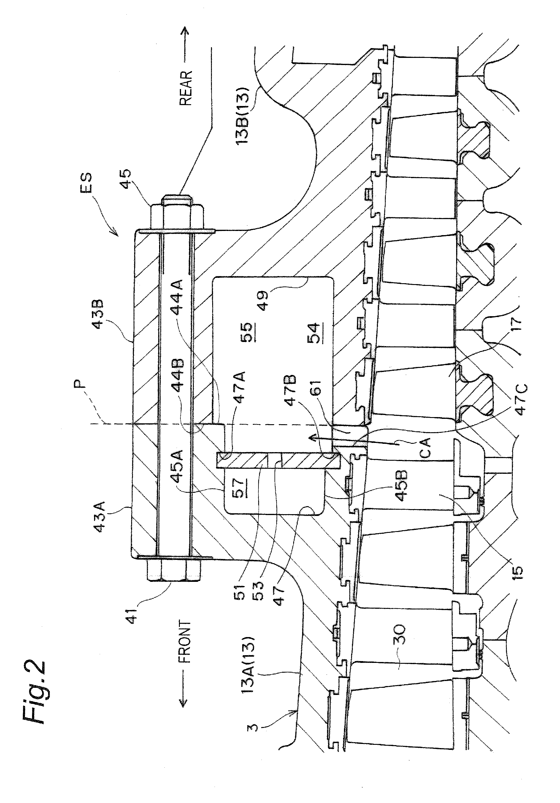
The gas turbine engine described in this patent has an extraction structure that allows for precise control of the small amount of air that is extracted. This is achieved through the use of a cylindrical housing with a plurality of first apertures and an annular partition with a plurality of second apertures, which results in an even pressure in the combustor. The size of the second apertures can be adjusted to vary the amount of extraction air. The engine also has a first extracting passage and a valve to control the air flow. The design of the housing and the assembly of the parts create a sealing engagement to prevent air leakage. Overall, this extraction structure ensures accurate control and even pressure in the compressor.

Problems solved by technology

On the other hand, the technique requires that the various sizes of slits are formed integrally in the compressor housing, which complicates design modifications of the slits according to the requirement of change in the amount of air.
This complicates a dimension control of, in particular, narrow slits for extracting smaller amount of air, which needs elevated size precisions.
Therefore, an even pressure distribution may not be obtained within the interior of the compressor.

Method used


Image

  • Structure for extracting compressed air from compressor of gas turbine engine and gas turbine engine with the structure
  • Structure for extracting compressed air from compressor of gas turbine engine and gas turbine engine with the structure
  • Structure for extracting compressed air from compressor of gas turbine engine and gas turbine engine with the structure

Examples


Embodiment Construction

[0024]With reference to the accompanying drawings, a preferred embodiment according to the invention will be described below.

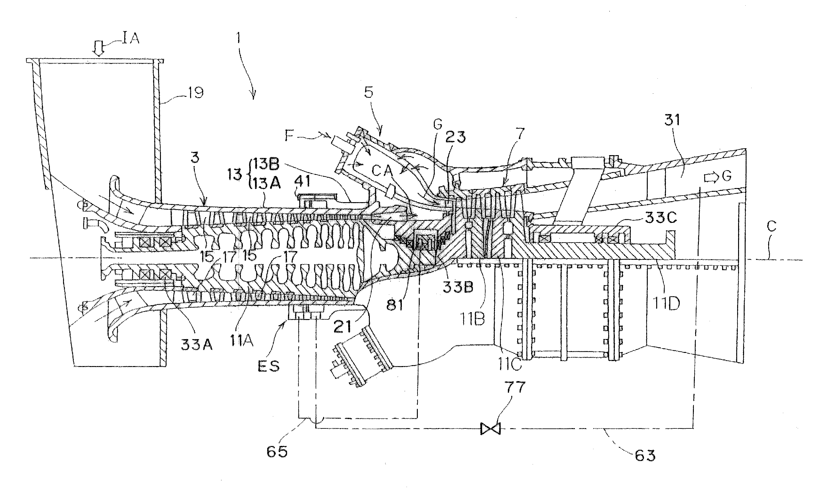
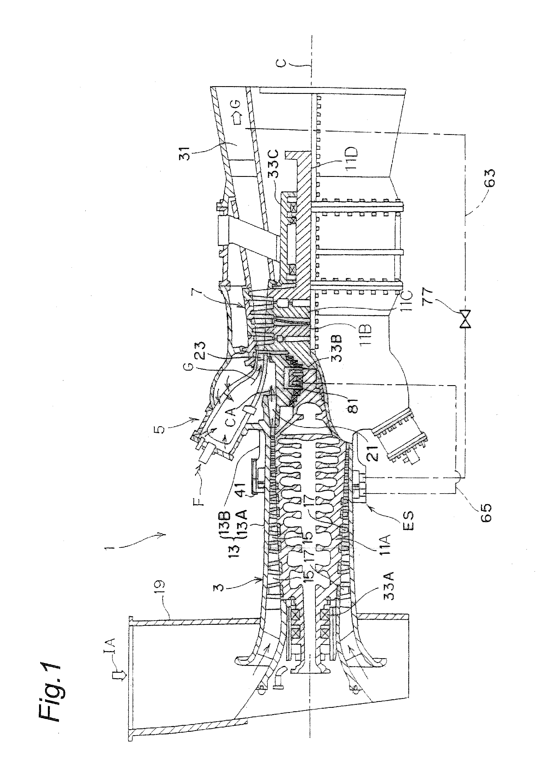
[0025]FIG. 1 shows a partially broken-away side elevation of a gas turbine engine (hereinafter referred to as “engine”) which incorporates an extracting structure according to an embodiment of the invention. The engine 1 comprises compressor 3, combustors 5 and turbine 7 so that an intake air IA is compressed by the compressor 3 and then supplied to the combustors 5 where it is combusted with fuel F injected into the combustors 5 to generate a high-temperature and high-pressure combustion gas G which is used for driving the turbine 7. In the following descriptions, left and right sides of the engine 1 with respect to a longitudinal axis C in the drawing will be referred to as “front / upstream” and “rear / downstream”, respectively, as necessary.

[0026]According to the embodiment, the compressor 3 is an axial-flow compressor and comprises a compressor rotor 11A whi...


PUM


Abstract

Provided is a structure of a gas turbine engine for extracting a part of compressed air generated by a compressor. The structure comprises a cylindrical housing having an annular portion extending around the compressing chamber to define an annular chamber, an annular partition dividing the annular chamber into first and second plenum chambers. The cylindrical housing has first apertures to communicate between the compressing chamber and the first plenum chamber. The partition has second apertures to communicate between the first and second plenum chambers. The first and second apertures are configured so that that the first apertures have a first total cross-sectional area and the second apertures have a second total cross-sectional area which is smaller than the first total cross-sectional area.

Description

TECHNICAL FIELD[0001]The present invention relates to a structure for extracting a compressed air from a compressor of gas turbine engine. Also, the present invention relates to a gas turbine engine incorporating the structure.BACKGROUND OF THE INVENTION[0002]In a gas turbine engine with a multi-stage compressor, a compressed air generated by a compressor is in part used for the cooling of a turbine, for example. The compressed air is extracted from the compressor through a plurality of slits formed in a compressor housing at regular intervals in the circumferential direction so as to prevent a pressure drop in the air extracting zone and the resultant uneven pressure distribution in the compressor with respect to the circumferential direction.[0003]For this purpose, JP 2001-304194 (A) discloses to provide various sizes of slits in order to extract various amounts of compressed air depending on usages of the extracted air. This technique may be advantageous in that a suitable pressu...

Claims


Application Information

Patent Timeline
Patent Type & Authority Applications(United States)
IPC IPC(8): F02G3/00
CPCF04D27/023F02C6/08F02C9/18F04D27/0207F04D27/0215F04D29/522
Inventor SAKAI, YUSUKEIKEGUCHI, TAKUYATERAUCHI, KOJI
Owner KAWASAKI HEAVY IND LTD
Learn More