
Optical Receiver with Reduced Cavity Size and Methods of Making and Using the Same

Active Publication Date: 2013-02-21
SOURCE PHOTONICS
View PDF14 Cites 12 Cited by
  • Summary
  • Abstract
  • Description
  • Claims
  • Application Information

AI Technical Summary

Benefits of technology

The present invention is about an optical device that can make optical signal processing components smaller, which will make the device smaller and more compact. This will allow for more functionality to be included in a smaller package. By arranging components of the device in a specific way, the device can have a smaller size.

Problems solved by technology

However, the optical and optoelectronic network equipment industries seek ever-smaller transceiver packages and / or consumption of less space by functional components in the transceiver.

Method used


Image

  • Optical Receiver with Reduced Cavity Size and Methods of Making and Using the Same
  • Optical Receiver with Reduced Cavity Size and Methods of Making and Using the Same
  • Optical Receiver with Reduced Cavity Size and Methods of Making and Using the Same

Examples


Embodiment Construction

[0023]Reference will now be made in detail to various embodiments of the invention, examples of which are illustrated in the accompanying drawings. While the invention will be described in conjunction with the following embodiments, it will be understood that the descriptions are not intended to limit the invention to these embodiments. On the contrary, the invention is intended to cover alternatives, modifications and equivalents that may be included within the spirit and scope of the invention as defined by the appended claims. Furthermore, in the following detailed description, numerous specific details are set forth in order to provide a thorough understanding of the present invention. However, it will be readily apparent to one skilled in the art that the present invention may be practiced without these specific details. In other instances, well-known methods, procedures, components, and circuits have not been described in detail so as not to unnecessarily obscure aspects of th...


PUM

PropertyMeasurementUnit
Angleaaaaaaaaaa
Angleaaaaaaaaaa
Angleaaaaaaaaaa

Abstract

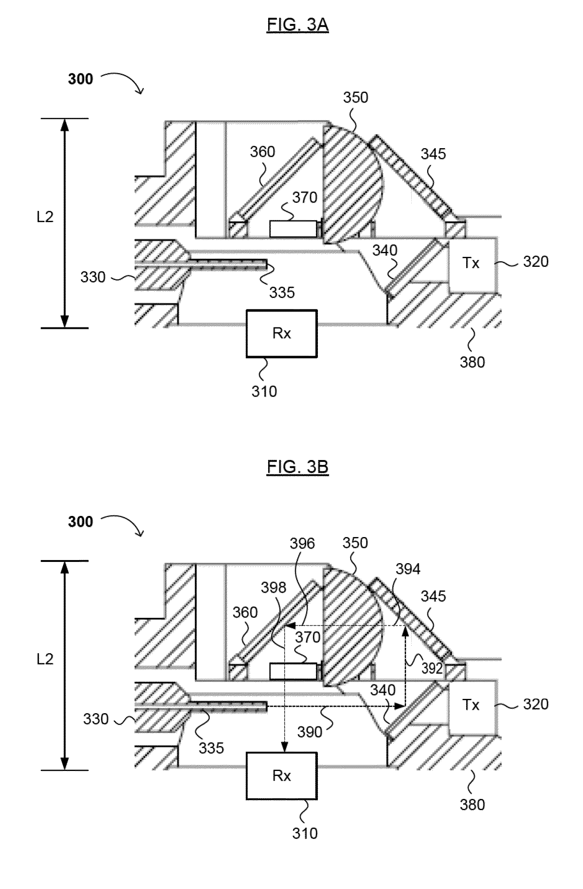
Methods for manufacturing and using an optical or optoelectronic device are disclosed. The optical or optoelectronic device and related methods may be useful as an optical or optoelectronic transceiver or for the processing of optical signals. The optical or optoelectronic device generally comprises a light-transmitting medium configured to transmit a first light beam; a light-receiving unit configured to receive and process a focused, reflected light beam; a first mirror or beam splitter configured to reflect at least a first portion of the transmitted light beam away from the light-receiving unit; a lens configured to focus the reflected light beam; and a second mirror configured to reflect the focused, reflected light beam towards the light-receiving unit.

Description

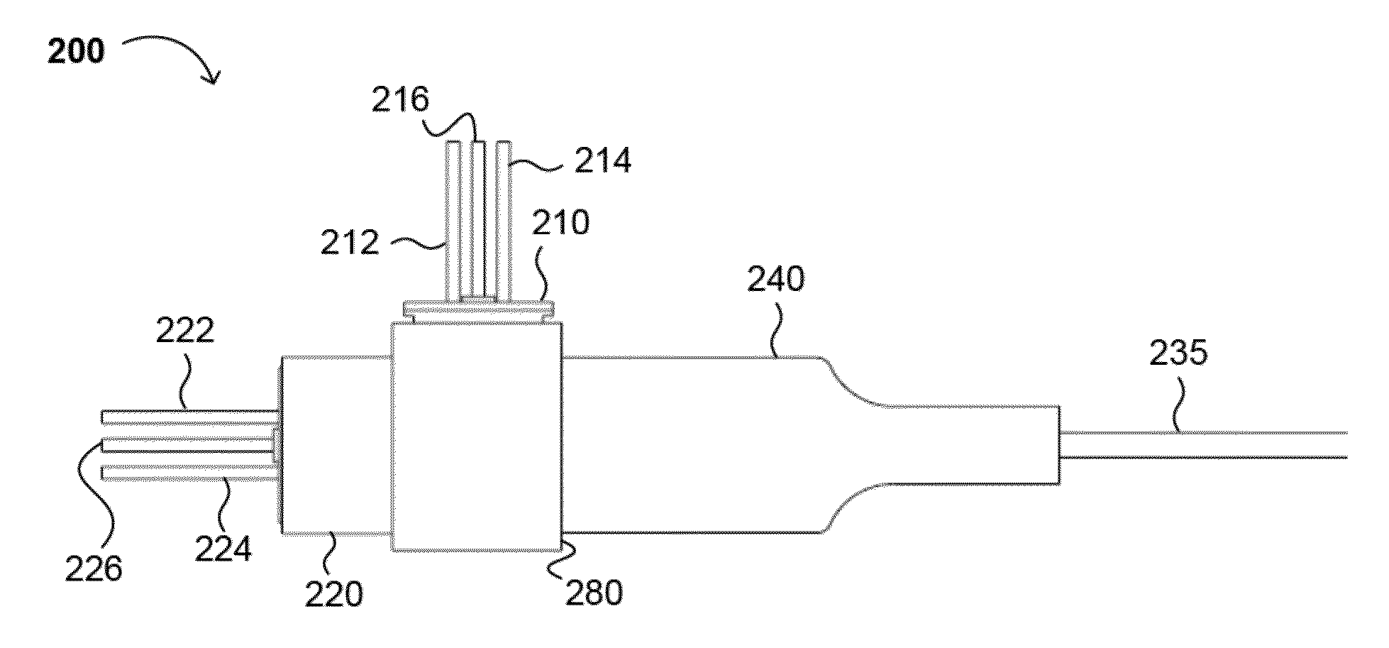
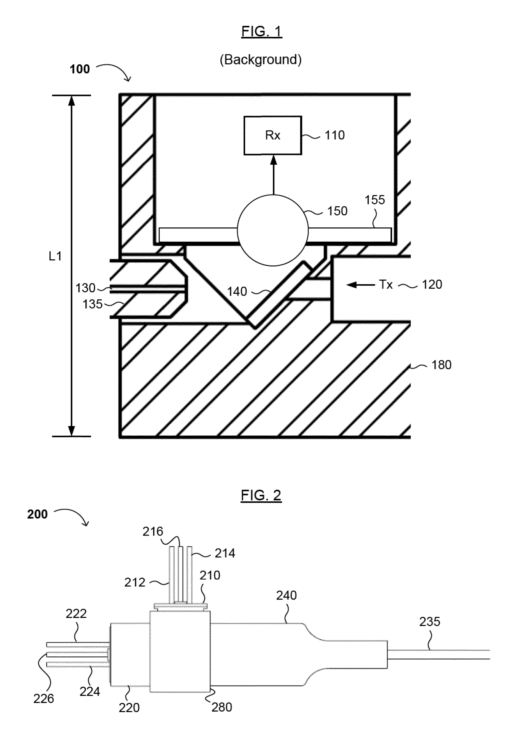
FIELD OF THE INVENTION[0001]The present invention generally relates to optical signal reception, and optionally, optical signal transmission. More specifically, embodiments of the present invention pertain to methods and apparatuses for receiving an optical signal using a light-processing cavity having a reduced size.DISCUSSION OF THE BACKGROUND[0002]FIG. 1 shows a portion of a conventional optical transceiver 100 having a housing 180. The optical transceiver 100 comprises a light-carrying medium 130 (e.g., an optical fiber) which transmits a received optical signal towards a beam splitter 140. At least a portion of the optical signal is reflected by beam splitter 140 towards a ball lens 150. The reflected portion of the light passes through the lens 150 and is received by a light-receiving unit 110 (e.g., a photodiode). The lens 150 is positioned in a lens cap 155. Thus, the housing 180 encompasses a light processing cavity in the optical transceiver 100.[0003]The transceiver 100 f...

Claims


Application Information

Patent Timeline
IPC IPC(8): G02B6/32B23P11/00
CPCG02B6/4206G02B6/4214Y10T29/49826G02B6/4215G02B6/4246G02B6/12019G02B6/12002G02B6/4201G02B6/12004G02B6/32G02B6/428
Inventor AMIT, MOSHE
Owner SOURCE PHOTONICS
Learn More