
Method and system for measuring amplitude and phase difference between two sinusoidal signals

Inactive Publication Date: 2013-02-21
SOFT DB
View PDF8 Cites 2 Cited by
  • Summary
  • Abstract
  • Description
  • Claims
  • Application Information

AI Technical Summary

Benefits of technology

[0010]There is further provided a phase-locked loop circuit driving a system excited by a sine generator in scanning-probe microscopy applications, the circuit comprising an adaptive filter determining and tracking coefficients a and b associated with a sample of a reference signal from the sine gener

Problems solved by technology

As a result, the filter limits the useful frequency range of the PLL to at most one octave.
If the filter is wide the frequency range is large and the time response

Method used


Image

  • Method and system for measuring amplitude and phase difference between two sinusoidal signals
  • Method and system for measuring amplitude and phase difference between two sinusoidal signals
  • Method and system for measuring amplitude and phase difference between two sinusoidal signals

Examples


Example

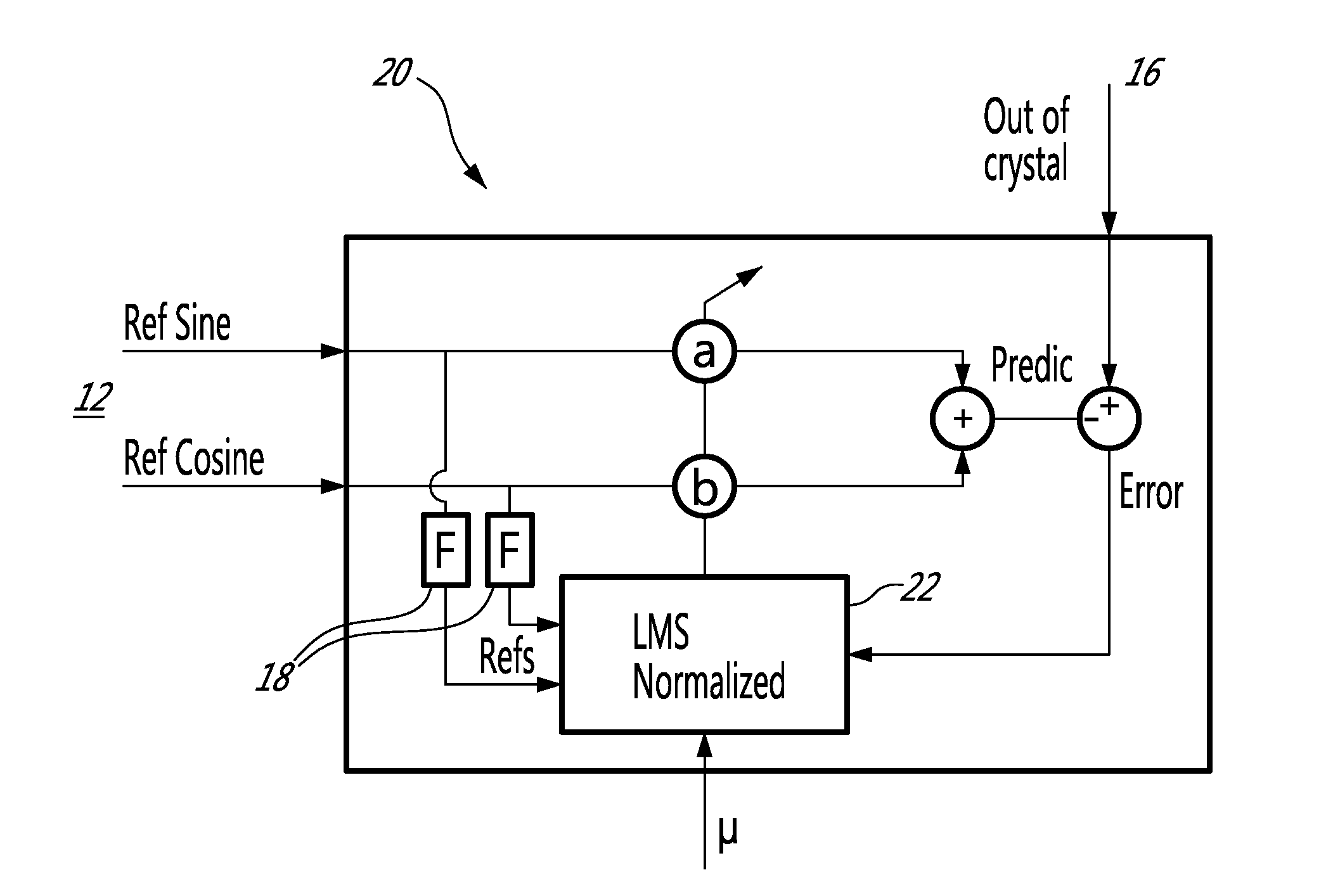
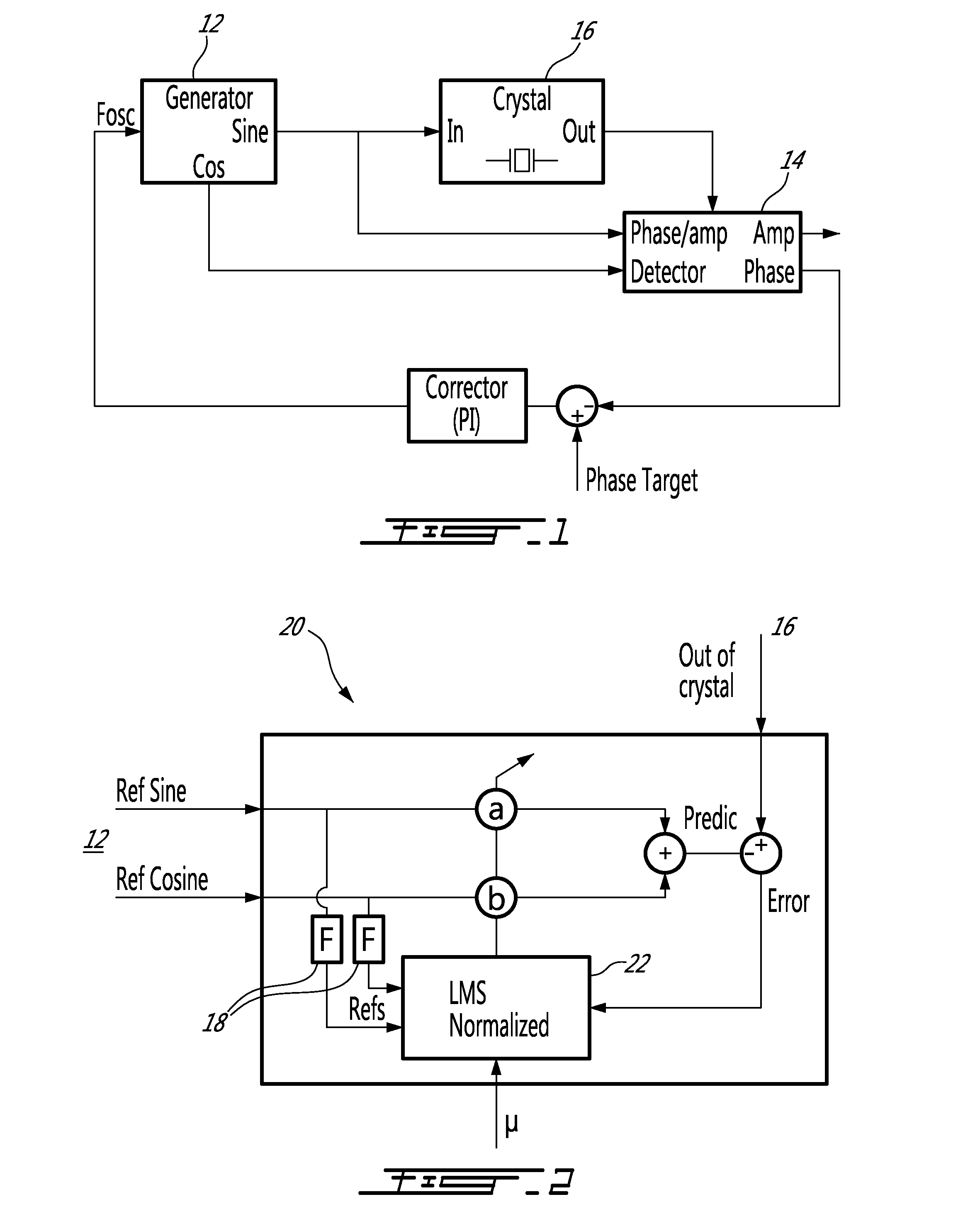
[0017]A detector 20 according to an embodiment of an aspect of the present invention is illustrated in FIG. 2, and will be described in an application such as PLL for illustrative purposes.

[0018]The detector 20 compares the signal from a sine generator, such as a variable-frequency oscillator 12 with the output signal from a system, such as a resonator 16, using an adaptive filter 22.

[0019]The sine generator 12 may be a sine / cosine generator of a recursive type (previously described in Fast and High-Precision Sine Generator for a TMS320C54x fixed-Point DSP Alex Boudreau, Bruno Paillard—Article published on the site of globaldsp.com.), for example, to provide a high-precision synthesis at a very low computational power.

[0020]The adaptive filter 22 determines coefficients a and b that minimize a prediction error on a sample of the output signal from the system 16, to estimate the output of the resonator 16 from a sample of the reference quadrature inputs Ref Sine, Ref Cosine.

[0021]The...


PUM


Abstract

A method and a system for measuring amplitude and phase difference between two sinusoidal signals, using an adaptive filter. The method generally comprises measuring a sample of an output signal of a system excited by a sample of a reference signal; using an adaptive filter and the sample of the reference signal to determine a and b coefficients that minimize a prediction error on the sample of the output signal, iteratively, and determining the amplitude and/or phase of the output of the system using the a and b coefficients.

Description

CROSS REFERENCE TO RELATED APPLICATIONS[0001]This application claims benefit, under 35 U.S.C. §119(e), of U.S. provisional application Ser. No. 61 / 525,231, filed on Aug. 19, 2011. All documents above are incorporated herein in their entirety by reference.FIELD OF THE INVENTION[0002]The present invention relates to measurement in the context of digital signal processing. More specifically, the present invention is concerned with a method and system for measuring amplitude and phase difference between two sinusoidal signals.BACKGROUND OF THE INVENTION[0003]The measurement of the phase between two sinusoidal signals, or phase detection, has a primary role in a number of signal processing applications.[0004]Phase-Locked Loop (PLL) for example may be used in scanning-probe microscopy applications for example, such as Atomic-Force Microscopy, where the probe is a mechanical crystal or resonator which resonance characteristics change as it gets close to the scanned surface. In such an appl...

Claims


Application Information

Patent Timeline
IPC IPC(8): H03L7/06G01R19/165G01R25/00
CPCH03L7/02G01R25/00
Inventor PAILLARD, BRUNOBOUDREAU, ALEX
Owner SOFT DB
Learn More